


Installing a Cisco 12008 3-23
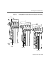
Connecting Route Processor Cables
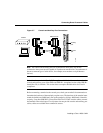
GRP Auxiliary Port Signals
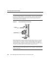
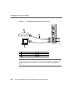
The auxiliary port on the GRP is a DB-25 plug DTE port for connecting a modem or other
DCE device (such as a CSU/DSU or other router) to the Cisco 12008. The port is located
above the console port on the GRP faceplate. The auxiliary port supports hardware flow
control and modem control. An example of a modem connection is shown in Figure 3-7.
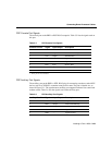
Table 3-2 lists the signals used on the auxiliary port.
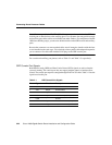
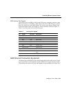
Table 3-2 Auxiliary Port Signals
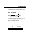
GRP Ethernet Connection Equipment
The Ethernet port on the GRP has both a media independent interface (MII), 40-pin, D-shell
type receptacle and a media dependent interface (MDI) RJ-45 receptacle that are capable
of data transmission rates from 10 and 100 megabits per second (Mbps). (See Figure 3-8.)
Pin Signal Direction Description
1 Signal Ground – Signal Ground
2 TxD Output Transmit Data
3 RxD Input Receive Data
4 RTS Output Request To Send (used for hardware flow control)
5 CTS Input Clear To Send (used for hardware flow control)
6 DSR Input Data Set Ready
7 Signal Ground – Signal Ground
8 CD Input Carrier Detect (used for modem control)
20 DTR Output Data Terminal Ready (used for modem control
only)
22 RING Input Ring