


Adding, Removing, or Replacing a DC-Input Power Supply
Cisco 12008 Gigabit Switch Router Installation and Configuration Guide
7-36
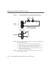
Step 24 Before connecting each cable to the appropriate terminals on the power supply
faceplate, remove the tape (that you applied in Step 10 above) from the lug.
Strictly observe the following order in reconnecting the leads to the power
supply terminals:
(a) Ground
(b) + (positive)
(c) – (negative)
Step 25 Secure each cable to the terminals using the previously removed lock washers
and nuts. Tighten the lock washers and nuts on each terminal using a 10 mm
nutdriver (or a 1/4-inch socket wrench with a 10 mm deep-well socket).
Caution Do not overtighten the nuts on the power supply terminals.
Step 26 If you intend to reconnect the external alarm monitoring facility to the circuit
breaker alarm terminal block on the new power supply, reconnect the leads as
they were on the old power supply (see Step 11).
Step 27 Remove the tape securing the main source DC circuit breaker in the OFF (0)
position (see Step 3).
Step 28 Set the main source DC circuit breaker to the ON (1) position.
Step 29 Set the rotary power switch on the new DC-input power supply to the ON (|)
position.
To verify that the new DC-input power supply is operating properly, perform the procedure
in the following section.