


Adding, Removing, or Replacing a DC-Input Power Supply
Cisco 12008 Gigabit Switch Router Installation and Configuration Guide
7-34
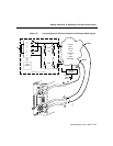
Step 11 If an external alarm monitoring facility is attached to the circuit breaker alarm
terminal block on the power supply faceplate (see Figure 7-9), make a note of
how the leads are connected. Doing so enables you to properly identify each lead
for later reconnection.
Step 12 Disconnect the leads from the circuit breaker alarm terminal block.
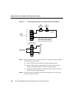
Step 13 Using a 1/4-inch flat-blade screwdriver, loosen the captive installation screw on
the power supply faceplate (see Figure 7-6).
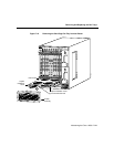
Step 14 Grasp the power supply carrying handle with your left hand and pull the unit
halfway out of the bay to disengage the blind-mating connector at the back of
the power supply from the backplane.
Warning The DC-input power supply weighs 14 lb (6.36 kg). For safety, use both hands
to withdraw the unit from the bay.
Step 15 Place your right hand beneath the power supply to support its weight and
completely withdraw the unit from the bay.
Step 16 Pending further action, set the unit aside in a safe place.
If you intend to return the removed power supply to the factory for repair or
replacement, restore the nuts and lock washers to the power supply terminals,
and reinstall the plastic safety shield (see Figure 7-7) on the faceplate standoffs.
Repackage the unit properly for return shipment using the original packing
materials, if available.
Step 17 On the new DC-input power supply that you intend to install in the now vacant
power supply bay, set the rotary power switch on the power supply faceplate to
the OFF (0) position.
Step 18 Grasp the carrying handle on the power supply with one hand; place your free
hand beneath the unit to support its weight.
Step 19 Position the unit appropriately for insertion into the power supply bay.