


9-6
Cisco ME 3400 Ethernet Access Switch Software Configuration Guide
78-17058-01
Chapter 9 Configuring Interface Characteristics
Understanding Interface Types
EtherChannel Port Groups
EtherChannel port groups treat multiple switch ports as one switch port. These port groups act as a single
logical port for high-bandwidth connections between switches or between switches and servers. An
EtherChannel balances the traffic load across the links in the channel. If a link within the EtherChannel
fails, traffic previously carried over the failed link changes to the remaining links. You can group
multiple trunk ports into one logical trunk port, group multiple access ports into one logical access port,
group multiple tunnel ports into one logical tunnel port, or group multiple routed ports into one logical
routed port. Most protocols operate over either single ports or aggregated switch ports and do not
recognize the physical ports within the port group. Exceptions are the Cisco Discovery Protocol (CDP),
Link Aggregation Control Protocol (LACP), and the Port Aggregation Protocol (PAgP), which operate
only on physical NNI ports.
When you configure an EtherChannel, you create a port-channel logical interface and assign an interface
to the EtherChannel. For Layer 3 interfaces, you manually create the logical interface by using the
interface port-channel global configuration command. Then you manually assign an interface to the
EtherChannel by using the channel-group interface configuration command. For Layer 2 interfaces, use
the channel-group interface configuration command to dynamically create the port-channel logical
interface. This command binds the physical and logical ports together. For more information, see
Chapter 31, “Configuring EtherChannels.”
Connecting Interfaces
Devices within a single VLAN can communicate directly through any switch. Ports in different VLANs
cannot exchange data without going through a routing device. With a standard Layer 2 switch, ports in
different VLANs have to exchange information through a router.
By default, the Cisco ME switch provides VLAN isolation between UNIs. UNIs cannot exchange traffic
unless they are changed to NNIs or assigned to a UNI community VLAN.
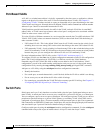
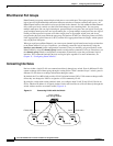
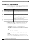
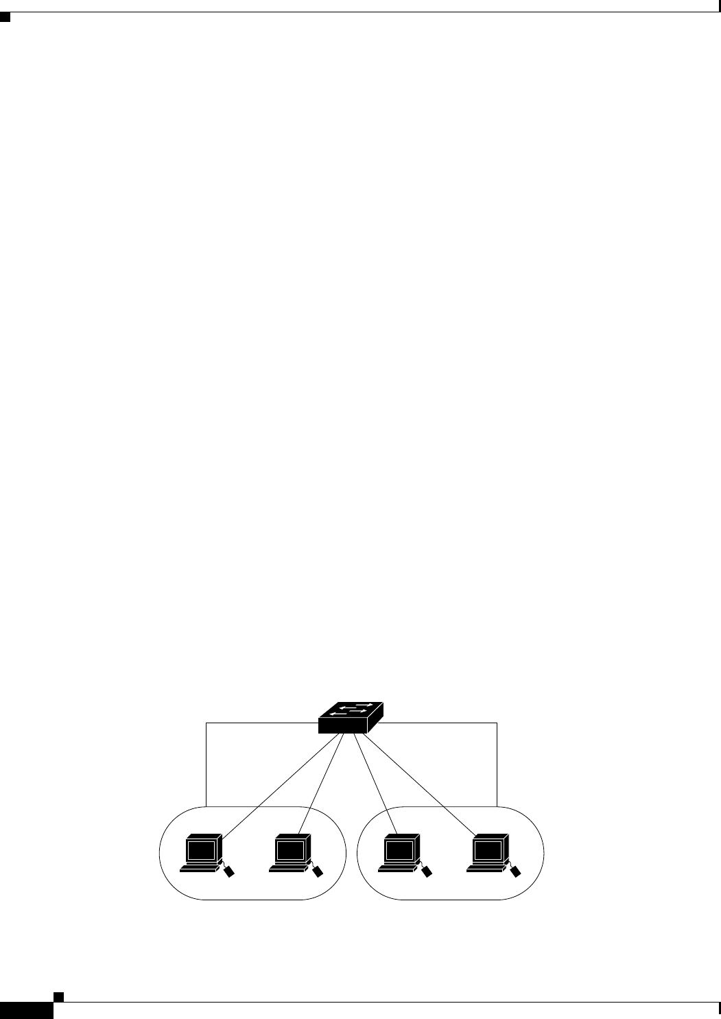
By using the switch with routing enabled, when you configure both VLAN 20 and VLAN 30 with an
SVI to which an IP address is assigned, packets can be sent from Host A to Host B directly through the
switch with no need for an external router (Figure 9-1).
Figure 9-1 Connecting VLANs with the Switch
Host A
SVI 1172.20.128.1 172.20.129.1SVI 2
Layer 3 switch
with routing enabled
VLAN 20
Host B
VLAN 30
101350