


20-19
Cisco ME 3400 Ethernet Access Switch Software Configuration Guide
78-17058-01
Chapter 20 Configuring IGMP Snooping and MVR
Configuring MVR
MVR Configuration Guidelines and Limitations
Follow these guidelines when configuring MVR:
• Receiver ports can only be access ports; they cannot be trunk ports. Receiver ports on a switch can
be in different VLANs, but should not belong to the multicast VLAN.
• The maximum number of multicast entries (MVR group addresses) that can be configured on a
switch (that is, the maximum number of television channels that can be received) is 256.
• MVR multicast data received in the source VLAN and leaving from receiver ports has its
time-to-live (TTL) decremented by 1 in the switch.
• Because MVR on the switch uses IP multicast addresses instead of MAC multicast addresses,
aliased IP multicast addresses are allowed on the switch. However, if the switch is interoperating
with Catalyst 3550 or Catalyst 3500 XL switches, you should not configure IP addresses that alias
between themselves or with the reserved IP multicast addresses (in the range 224.0.0.xxx).
• Do not configure MVR on private VLAN ports.
• MVR is not supported when multicast routing is enabled on a switch. If you enable multicast routing
and a multicast routing protocol while MVR is enabled, MVR is disabled, and you receive a warning
message. If you try to enable MVR while multicast routing and a multicast routing protocol are
enabled, the operation to enable MVR is cancelled, and you receive an error message.
• MVR can coexist with IGMP snooping on a switch.
• MVR data received on an MVR receiver port is not forwarded to MVR source ports.
• MVR does not support IGMPv3 messages.
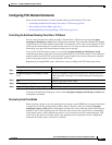
Configuring MVR Global Parameters
You do not need to set the optional MVR parameters if you choose to use the default settings. If you do
want to change the default parameters (except for the MVR VLAN), you must first enable MVR.
Note For complete syntax and usage information for the commands used in this section, see the command
reference for this release.
Beginning in privileged EXEC mode, follow these steps to configure MVR parameters:
Command Purpose
Step 1
configure terminal Enter global configuration mode.
Step 2
mvr Enable MVR on the switch.
Step 3
mvr group ip-address [count] Configure an IP multicast address on the switch or use the count parameter to
configure a contiguous series of MVR group addresses (the range for count is
1 to 256; the default is 1). Any multicast data sent to this address is sent to all
source ports on the switch and all receiver ports that have elected to receive
data on that multicast address. Each multicast address would correspond to
one television channel.