


24-2
Cisco ME 3400 Ethernet Access Switch Software Configuration Guide
78-17058-01
Chapter 24 Configuring SPAN and RSPAN
Understanding SPAN and RSPAN
These sections contain this conceptual information:
• Local SPAN, page 24-2
• Remote SPAN, page 24-2
• SPAN and RSPAN Concepts and Terminology, page 24-3
• SPAN and RSPAN Interaction with Other Features, page 24-8
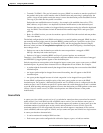
Local SPAN
Local SPAN supports a SPAN session entirely within one switch; all source ports or source VLANs and
destination ports reside in the same switch. Local SPAN copies traffic from one or more source ports in
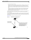
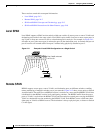
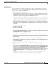
any VLAN or from one or more VLANs to a destination port for analysis. For example, in Figure 24-1,
all traffic on port 5 (the source port) is mirrored to port 10 (the destination port). A network analyzer on
port 10 receives all network traffic from port 5 without being physically attached to port 5.
Figure 24-1 Example of Local SPAN Configuration on a Single Switch
Remote SPAN
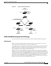
RSPAN supports source ports, source VLANs, and destination ports on different switches, enabling
remote monitoring of multiple switches across your network. Figure 24-2 shows source ports on Switch
A and Switch B. The traffic for each RSPAN session is carried over a user-specified RSPAN VLAN that
is dedicated for that RSPAN session in all participating switches. The RSPAN traffic from the source
ports or VLANs is copied into the RSPAN VLAN and forwarded over trunk ports carrying the RSPAN
VLAN to a destination session monitoring the RSPAN VLAN. Each RSPAN source switch must have
either ports or VLANs as RSPAN sources. The destination is always a physical port, as shown on Switch
C in the figure.
1 2 3 4 5 6 7 8 9 10 11 12
Port 5 traffic mirrored
on Port 10
3
2
1
4
5
67
8
9
11
12
10
Network analyzer
43580