


18-9
Cisco ME 3400 Ethernet Access Switch Software Configuration Guide
78-17058-01
Chapter 18 Configuring DHCP Features and IP Source Guard
Configuring DHCP Features
Specifying the Packet Forwarding Address
If the DHCP server and the DHCP clients are on different networks or subnets and the switch is running
the metro IP access image, you must configure the switch with the ip helper-address address interface
configuration command. The general rule is to configure the command on the Layer 3 interface closest
to the client. The address used in the ip helper-address command can be a specific DHCP server IP
address, or it can be the network address if other DHCP servers are on the destination network segment.
Using the network address enables any DHCP server to respond to requests.
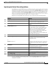
Beginning in privileged EXEC mode, follow these steps to specify the packet forwarding address:
To remove the DHCP packet forwarding address, use the no ip helper-address address interface
configuration command.
Command Purpose
Step 1
configure terminal Enter global configuration mode.
Step 2
interface vlan vlan-id Create a switch virtual interface by entering a VLAN
ID, and enter interface configuration mode.
Step 3
ip address ip-address subnet-mask Configure the interface with an IP address and an IP
subnet.
Step 4
ip helper-address address Specify the DHCP packet forwarding address.
The helper address can be a specific DHCP server
address, or it can be the network address if other
DHCP servers are on the destination network
segment. Using the network address enables other
servers to respond to DHCP requests.
If you have multiple servers, you can configure one
helper address for each server.
Step 5
exit Return to global configuration mode.
Step 6
interface range port-range
or
interface interface-id
Configure multiple physical ports that are connected
to the DHCP clients, and enter interface range
configuration mode.
or
Configure a single physical port that is connected to
the DHCP client, and enter interface configuration
mode.
Step 7
no shutdown Enable the interface(s), if necessary. By default, user
network interfaces (UNIs) are disabled and network
node interfaces (NNIs) are enabled.
Step 8
switchport mode access Define the VLAN membership mode for the port.
Step 9
switchport access vlan vlan-id Assign the ports to the same VLAN as configured in
Step 2.
Step 10
end Return to privileged EXEC mode.
Step 11
show running-config Verify your entries.
Step 12
copy running-config startup-config (Optional) Save your entries in the configuration file.