


32-62
Cisco ME 3400 Ethernet Access Switch Software Configuration Guide
78-17058-01
Chapter 32 Configuring IP Unicast Routing
Configuring Multi-VRF CE
• Multi-VRF CE lets multiple customers share the same physical link between the PE and the CE.
Trunk ports with multiple VLANs separate packets among customers. Each customer has its own
VLAN.
• Multi-VRF CE does not support all MPLS-VRF functionality. It does not support label exchange,
LDP adjacency, or labeled packets.
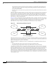
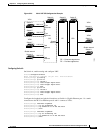
• For the PE router, there is no difference between using multi-VRF CE or using multiple CEs. In
Figure 32-5, multiple virtual Layer 3 interfaces are connected to the multi-VRF CE device.
• The switch supports configuring VRF by using physical ports, VLAN SVIs, or a combination of
both. The SVIs can be connected through an access port or a trunk port.
• A customer can use multiple VLANs as long as they do not overlap with those of other customers.
A customer’s VLANs are mapped to a specific routing table ID that is used to identify the
appropriate routing tables stored on the switch.
• The switch supports one global network and up to 26 VRFs.
• Most routing protocols (BGP, OSPF, RIP, EIGRP, and static routing) can be used between the CE
and the PE. However, we recommend using external BGP (EBGP) for these reasons:
–
BGP does not require multiple algorithms to communicate with multiple CEs.
–
BGP is designed for passing routing information between systems run by different
administrations.
–
BGP makes it easy to pass attributes of the routes to the CE.
• Multi-VRF CE does not affect the packet switching rate.
• VPN multicast is not supported.
• If no VRFs are configured then 104 policies can be configured.
• If even one VRF is configured than 41 policies can be configured.
• If more than 41 policies are configured then VRF cannot be configured.
• VRF and private VLANs are mutually-exclusive. You cannot enable VRF on a private VLAN.
Similarly, you cannot enable private VLAN on a VLAN with VRF configured on the VLAN
interface.
• VRF and policy-based routing (PBR) are mutually-exclusive on a switch interface. You cannot
enable VRF when PBR is enabled on an interface. In contrast, you cannot enable PBR when VRF is
enabled on an interface.
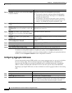
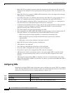
Configuring VRFs
Beginning in privileged EXEC mode, follow these steps to configure one or more VRFs. For complete
syntax and usage information for the commands, refer to the switch command reference for this release
and the Cisco IOS Switching Services Command Reference, Release 12.2.
Command Purpose
Step 1
configure terminal Enter global configuration mode.
Step 2
ip routing Enable IP routing.
Step 3
ip vrf vrf-name Name the VRF, and enter VRF configuration mode.