


13-10
Cisco ME 3400 Ethernet Access Switch Software Configuration Guide
78-17058-01
Chapter 13 Configuring IEEE 802.1Q and Layer 2 Protocol Tunneling
Configuring Layer 2 Protocol Tunneling
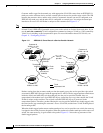
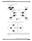
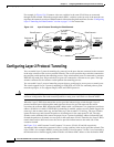
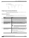
For example, in Figure 13-6, Customer A has two switches in the same VLAN that are connected
through the SP network. When the network tunnels PDUs, switches on the far ends of the network can
negotiate the automatic creation of EtherChannels without needing dedicated lines. See the “Configuring
Layer 2 Tunneling for EtherChannels” section on page 13-14 for instructions.
Figure 13-6 Layer 2 Protocol Tunneling for EtherChannels
Configuring Layer 2 Protocol Tunneling
You can enable Layer 2 protocol tunneling (by protocol) on the ports that are connected to the customer
in the edge switches of the service-provider network. The service-provider edge switches connected to
the customer switch perform the tunneling process. Edge-switch tunnel ports are connected to customer
IEEE 802.1Q trunk ports. Edge-switch access ports are connected to customer access ports. The edge
switches connected to the customer switch perform the tunneling process.
You can enable Layer 2 protocol tunneling on ports that are configured as access ports or tunnel ports.
The switch supports Layer 2 protocol tunneling for CDP, STP, and VTP. For emulated point-to-point
network topologies, it also supports PAgP, LACP, and UDLD protocols.
Caution PAgP, LACP, and UDLD protocol tunneling is only intended to emulate a point-to-point topology. An
erroneous configuration that sends tunneled packets to many ports could lead to a network failure.
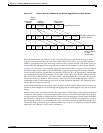
When the Layer 2 PDUs that entered the service-provider inbound edge switch through a Layer 2
protocol-enabled port exit through the trunk port into the service-provider network, the switch
overwrites the customer PDU-destination MAC address with a well-known Cisco proprietary multicast
address (01-00-0c-cd-cd-d0). If IEEE 802.1Q tunneling is enabled, packets are also double-tagged; the
outer tag is the customer metro tag, and the inner tag is the customer’s VLAN tag. The core switches
ignore the inner tags and forward the packet to all trunk ports in the same metro VLAN. The edge
switches on the outbound side restore the proper Layer 2 protocol and MAC address information and
forward the packets to all tunnel or access ports in the same metro VLAN. Therefore, the Layer 2 PDUs
remain intact and are delivered across the service-provider infrastructure to the other side of the
customer network.
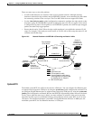
See Figure 13-4, with Customer X and Customer Y in access VLANs 30 and 40, respectively.
Asymmetric links connect the customers in Site 1 to edge switches in the service-provider network. The
Layer 2 PDUs (for example, BPDUs) coming into Switch 2 from Customer Y in Site 1 are forwarded to
the infrastructure as double-tagged packets with the well-known MAC address as the destination MAC
Switch A
VLAN 17
VLAN 18
VLAN 19
VLAN 20
VLAN 17
VLAN 18
VLAN 19
VLAN 20
Switch B
Switch C
Service
Provider
EtherChannel 1
Customer A
Site 1
Customer A
Site 2
101844
Switch D
EtherChannel 1
Trunk
Asymmetric link