


11-20
Cisco ME 3400 Ethernet Access Switch Software Configuration Guide
78-17058-01
Chapter 11 Configuring VLANs
Configuring VLAN Trunks
Load Sharing Using STP Port Priorities
When two ports on the same switch form a loop, the switch uses the STP port priority to decide which
port is enabled and which port is in a blocking state. You can set the priorities on a parallel NNI trunk
port so that the port carries all the traffic for a given VLAN. The NNI trunk port with the higher priority
(lower values) for a VLAN is forwarding traffic for that VLAN. The NNI trunk port with the lower
priority (higher values) for the same VLAN remains in a blocking state for that VLAN. One trunk port
sends or receives all traffic for the VLAN.
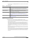
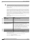
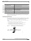
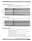
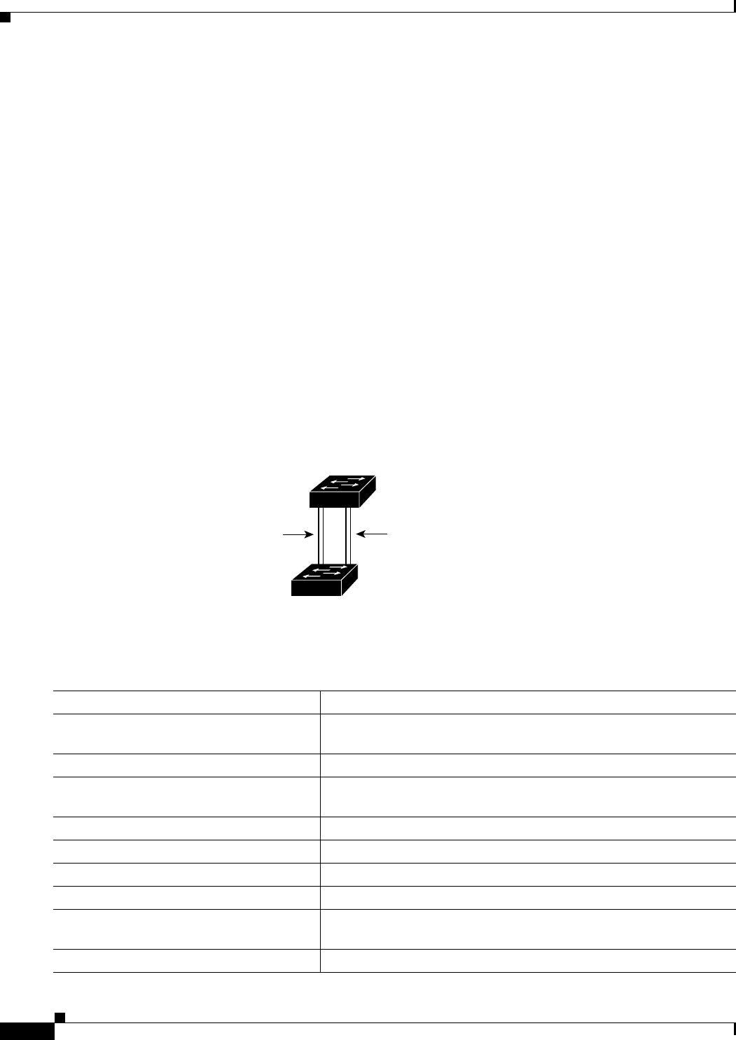
Figure 11-3 shows two trunks connecting supported switches. In this example, the switches are
configured as follows:
• VLANs 8 through 10 are assigned a port priority of 16 on Trunk 1.
• VLANs 3 through 6 retain the default port priority of 128 on Trunk 1.
• VLANs 3 through 6 are assigned a port priority of 16 on Trunk 2.
• VLANs 8 through 10 retain the default port priority of 128 on Trunk 2.
In this way, Trunk 1 carries traffic for VLANs 8 through 10, and Trunk 2 carries traffic for VLANs 3
through 6. If the active trunk fails, the trunk with the lower priority takes over and carries the traffic for
all of the VLANs. No duplication of traffic occurs over any trunk port.
Figure 11-3 Load Sharing by Using STP Port Priorities
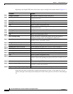
Beginning in privileged EXEC mode on Switch A, follow these steps to configure the network shown in
Figure 11-3. Note that you can use any interface numbers; those shown are examples only.
93370
Switch A
Switch B
Trunk 2
VLANs 3 – 6 (priority 16)
VLANs 8 – 10 (priority 128)
Trunk 1
VLANs 8 – 10 (priority 16)
VLANs 3 – 6 (priority 128)
Command Purpose
Step 8
show vlan Verify that the referenced VLANs exist on Switch A. If not, create the
VLANs by entering the VLAN IDs.
Step 9
configure terminal Enter global configuration mode.
Step 10
interface gigabitethernet 0/1 Define the interface to be configured as the Trunk 1 interface, and
enter interface configuration mode.
Step 11
port-type nni Configure the interface as an NNI. UNIs do not support STP.
Step 12
switchport mode trunk Configure the port as a trunk port.
Step 13
spanning-tree vlan 8-10 port-priority 16 Assign the port priority of 16 for VLANs 8 through 10 on Trunk 1.
Step 14
end Return to privileged EXEC mode.
Step 15
show interfaces gigabitethernet 0/1
switchport
Verify the port configuration.
Step 16
configure terminal Enter global configuration mode.