


Chapter 6 Cabling the Line Ports and Completing the Installation
Connecting the line ports to the network
SCE 2000 4xGBE Installation and Configuration Guide
6-8 OL-7824-02
Connecting the GBE Line Interface Ports
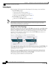
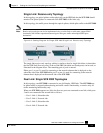
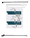
The following sections present the general procedure for cabling the GBE interface ports. Refer to
Cabling Diagrams (on page 6-2) to find the appropriate cabling diagram for the topology of your
system for the specific connections required.
Note
When installing an External Optical Bypass module, the SCE 2000 line ports are connected to the
module. See Cabling the External Optical Bypass Module (on page A-6) for complete instructions.
Fiber Specifications
The following table presents the fiber specifications. The SCE 2000 may be ordered with either
Multimode or Single Mode transceivers The transceiver type is indicated on the front panel under
the ports. Note that both transceivers on any individual SCE 2000 are the same, either 850nm
Multimode OR 1310nm Single Mode.
Table 6-1 Fiber Specifications
SCE Model Transceiver Transmit Power Receive Power Typical (Max.) Distance
SCE 2000 4xGBE
MM
850nm Multimode –9.5 to –4 dBm –17 to 0 dBm
• 750m for 50µm Core
Diameter MMF
• 400m for 62.5µm Core
Diameter MMF
SCE 2000 4xGBE
SM
1310nm FRP laser
Single Mode
–9.5 to –3 dBm –20 to 3 dBm 10 km for 9.0µm Core
Diameter SMF
Cabling the GBE Port
Warning
Class 1 laser. Avoid exposure to radiation and do not stare into open aperture.
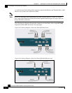
To cable the SCE 2000 GBE line port, complete the following steps:
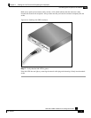
Step 1 Take the appropriate fiber optic cable (see Fiber Specifications (on page 6-8)) and plug it
into the appropriate GBE port on the front panel of the SCE 2000.