


Chapter 2 Overview of the SCE 2000 Platform
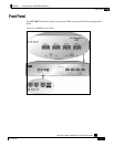
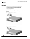
Front Panel
SCE 2000 4xGBE Installation and Configuration Guide
2-4 OL-7824-02
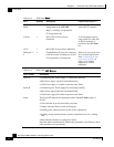
Table 2-2 SCE 2000 Ports
Port Quantity Description Connect This Port To…
Mng1/
Mng2
2 10/100/1000 Ethernet RJ-45 ports for
management of the SCE 2000.
Mng 2 is currently not operational.
CLI designation: 0/0.
A LAN using an FE cable
with an RJ-45 connector
Console 1 RS-232 RJ-45 port for use by
technicians
A local terminal (console)
using an RS-232 cable with
an RJ-45 connector, as
provided in the SCE 2000
kit.
AUX 1 RS-232 RJ-45 port used by technicians
GBE ports 1-
4
4 GigabitEthernet SC ports for connecting
to the line and/or cascading two devices
CLI designation: 0/1 through 0/4
Refer to Connecting the Line
Ports (Connecting the Line
Ports "Connecting the line
ports to the network" on
page 6-1) for cabling
diagrams for various
topologies
Table 2-3 SCE 2000 LED Groups
LED Groups Description
Power A
• Continuous green: Power supply A is functioning normally
• Red: Power supply A present, but malfunctioning
• Unlit: Power supply A is either not present or has failed.
Power B
• Continuous green: Power supply B is functioning normally
• Red: Power supply B present, but malfunctioning
• Unlit: Power supply B is either not present or has failed.
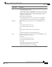
Status The Status LED indicates the operational status of the SCE 2000 system, as
follows:
• Unlit: indicates no power from either power unit.
• Orange: indicates that the system is booting up.
• Flashing green: indicates that the system is fully operational.
• Flashing orange: indicates that the system is operational, but is in a warning
state.
• Red: indicates that there is a problem or failure
Note that Alarms are hierarchical: Failure takes precedence over Warning, which
takes precedence over operational.