


Appendix A The External Optical Bypass Module
Installing the External Bypass Module
SCE 2000 4xGBE Installation and Configuration Guide
A-6 OL-7824-02
Cabling the External Optical Bypass Module
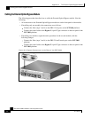
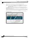
The following procedure describes how to cable the External Optical Bypass module. Note the
following:
• All connections to the External Optical Bypass module are on the front panel of the module.
• If installing only one module, the connections are as follows:
• Connect the fiber (steps 3 and 4) to the GBE-1 Line ports on the SCE 2000 platform.
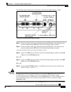
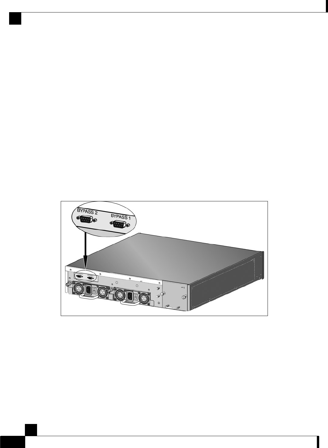
• Connect the control cable to the Bypass 1 9-pin D-Type connector on the rear panel of the
SCE 2000 platform.
• If installing two modules, repeat the entire procedure for the second module, with the
following changes:
• Connect the fiber (steps 3 and 4) to the GBE-2 Line/Cascade ports on the SCE 2000
platform.
• Connect the control cable to the Bypass 2 9-pin D-Type connector on the rear panel of the
SCE 2000 platform.
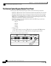
Figure A-4: Bypass Connectors on the Rear of the SCE 2000