


Chapter 5 Connecting the Management Interfaces and Performing Initial System Configuration
Connecting the Management Interface
SCE 2000 4xGBE Installation and Configuration Guide
OL-7824-02 5-27
Cabling the Management Port
The SCE 2000 has two management ports, labeled Mng1 and Mng 2. Use the Mng 1 port. The
Mng 2 port is currently not operational.
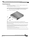
To cable the management port, complete the following steps:
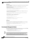
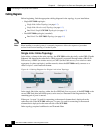
Step 1 Take the Ethernet cable provided (with attached RJ-45 connector) and plug it into the
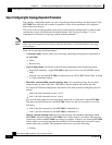
Mng 1 port on the front panel of the SCE 2000, as shown in the following figure.
Figure 5-2: Cabling the Management Port
Step 2
Connect the other end of the Ethernet cable into your management network.
Make sure that you push on the RJ-45 connector attached to the cable until you hear a click, which indicates
that the connector is fully inserted and secured in the receptacle. Gently pull on the plug to confirm whether
the plug is locked into the socket.
If the Link LED on the SCE 2000 management port does not light, try removing the cable and reinserting it
firmly into the module socket. To disconnect the plug from the socket, press down on the raised portion on
top of the plug, releasing the latch. You should hear an audible click indicating the latch has released.
Carefully pull the plug out of the socket.
If the management port Link LED on the SCE 2000 still does not light, verify that the cable is connected
correctly to the appropriate network element on its second end.
T