


Chapter 5 Connecting the Management Interfaces and Performing Initial System Configuration
Connecting the Management Interface
SCE 2000 4xGBE Installation and Configuration Guide
5-28 OL-7824-02
Verifying Management Interface Connectivity
If the SCE 2000 platform has been powered up, test now to verify that connectivity has been
established between the SCE 2000 and the remote management host. If the SCE 2000 platform is
not powered up, perform this step after starting the SCE 2000 platform.
To verify that connectivity has been established between the SCE 2000 and the remote
management host, complete the following steps:
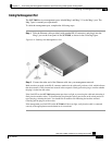
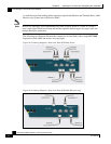
Step 1 After you connect the cable to the appropriate Mng port and to your network, check the
Mng 1 port LEDS.
There are two Mng LEDs: Link/Active, and 10/100/1000 (refer to Front Panel).
At this point, check that the Link/Active LED is green.
The state of the 10/100/1000 LED will depend on the Ethernet network settings.
Green indicates 100 Mbps and ‘Off’ indicates 10 Mbps.
Step 2
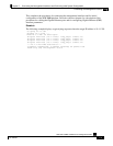
Test connectivity. From the host that you intend to use for remote management, ping to
the SCE 2000 by typing ping and the SCE 2000 IP address, and pressing Enter (see the
example, below).
Note
Please note that only step 2 above, is performed from the remote management host (Mng port
connection).
This verifies that an active connection exists between the specified station and the management port.
The ping program sends an echo request packet to an IP address and then awaits a reply. Ping output can
help you evaluate path-to-host reliability, delays over the path, and whether the host can be reached or is
functioning.