


Chapter 3 Topology
Physical Topologies
SCE 2000 4xGBE Installation and Configuration Guide
OL-7824-02 3-7
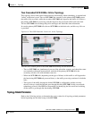
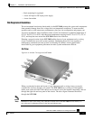
Two Cascaded SCE 2000s: Inline Topology
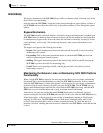
This topology allows both control and monitoring functionality where redundancy is required and
“inline” connection is used. The two SCE 2000s are cascaded, so the primary SCE 2000 process
the traffic of the two links, while the secondary SCE 2000 only bypasses the traffic of its links to
the primary SCE 2000 for processing, and then bypasses the processed traffic back to the link.
The two SCE 2000s also exchange keep-alive messages and subscriber state information.
In case the primary SCE 2000 fails, the two SCE 2000s switch their roles, and this way fail-over
is provided.
Figure 3-5: Two SCE Platforms: Dual Link Inline Topology
This fail-over solution preserves the SCE 2000 functionality and the network link:
• The two SCE 2000s are simultaneously aware of the subscriber contexts, and subscriber states
are constantly exchanged between them, such that if the primary SCE 2000 fails, the
secondary can take over with minimum state loss.
• When one SCE 2000 fails (depending on the type of failure) its link traffic is still bypassed to
the functioning SCE 2000 and processed there, so the traffic processing continues for both the
links.
• The bypass of the traffic through the failed SCE 2000 is configurable, and the user may
choose to always cutoff the line that goes through the failed SCE 2000. In this case network
redundancy protocols like HSRP are responsible for identifying the line cutoff and switching
all the traffic to go through the functioning SCE 2000.
Topology-Related Parameters
Refer to the following sections to determine the correct values for all topology-related parameters
before beginning run the initial setup of the SCE 2000.