


Chapter 4 Installation and Maintenance
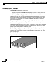
Power Supply Overview
SCE 2000 4xGBE Installation and Configuration Guide
4-18 OL-7824-02
Table 4-5 OK LED Status for AC-input and DC-input Power Supply Units
LED State Power Supply Unit Condition
On (green) The output voltage is in the required range (between 11.9 and 12.1 VDC).
Off The output voltage is not within the required range. (is greater than 12.1
VDC or less than 11.9 VDC)
Table 4-6 Power LED (on front panel) Status for AC-input and DC-input Power Supply
Units
LED State Power Supply Unit Condiiton
Continuous green Corresponding power supply unit is present and functioning normally
Red Corresponding power supply unit present, but malfunctioning
Unlit Corresponding power supply unit is either not present or has failed.
Note
Simple Network Management Protocol (SNMP) monitors the activity of the power supplies. In most
cases when a power supply problem occurs, an SNMP trap is sent in SNMP and the appropriate
message is posted on the SCE 2000 CLI.
Power Supply Specifications
The following table lists the AC-input and DC-input power supply specifications for the SCE
2000 platform:
Table 4-7 SCE 2000 Power Supply Specifications
AC-input power 200W maximum
AC-input voltage rating 100 to 240 VAC
AC-input current rating Rated for 4.5A when Vin = 100 VAC or 2A when Vin = 200 VAC
AC-input frequency rating 50 to 60 Hz
AC-input cable 18 AWG three-wire cable, with a three-lead IEC-320 receptacle on
the power supply end, and a country-dependent plug on the power
source end.
DC-input power 200W maximum
DC-input voltage rating –48/-60 VDC nominal (–36 to–72 VDC supply tolerance)
DC-input current rating 7A at –48 VDC
DC-input cable 12 AWG or 2.5-mm copper installation wire with hex or loop
connectors
DC-input circuit breaker One Fast 10A for each power supply unit