


Chapter 3 Topology
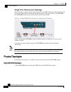
Physical Topologies
SCE 2000 4xGBE Installation and Configuration Guide
OL-7824-02 3-9
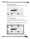
Physically Connected Links Parameter
If the system consists of more than one device, this parameter defines which link is connected to
this SCE 2000. Currently the system supports a maximum of two links, which are designated link
0 and link 1.
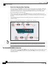
Priority
In a cascade topology, the user must define the priority of each SCE 2000.
• Primary: The Primary SCE 2000 is active by default
• Secondary: The Secondary SCE 2000 is the default standby.
Note that these defaults apply only when both devices are started together. However, if the
primary SCE 2000 fails and then recovers, it will not revert to active status, but remains in
standby status, while the secondary device remains active.
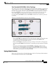
On-Failure Mode Parameter
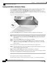
As described in the section The Bypass Mechanism, the bypass card supports four different
modes. The following two modes are possible when the SCE 2000 is not operational due to
platform failure or boot:
• Bypass: The optical splitter forwards traffic with no intervention of the control application
running in the SCE 2000 platform, but monitoring functions continue uninterrupted.
• Cutoff: There is no forwarding of traffic. The link is forced down, resulting in traffic cutoff at
Layer1.
The Forwarding mode enables control of traffic flow and is not compatible with the non-
operational status.
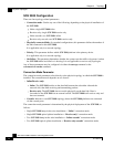
In a single SCE 2000 topology, the value of this parameter is determined by whether or not the
link can be completely cut when the SCE 2000 fails, or whether traffic flow should continue
across the link in spite of platform failure.
• Cutoff mode is required for the following:
• Redundant bump-in-the-wire topology.
• Non-redundant bump-in-the-wire topology if value-added services are crucial and are
more important than maintaining connectivity.
• Bypass mode is required for the following:
• Non-redundant bump-in-the-wire topology if connectivity is crucial.