


Chapter 5 Connecting the Management Interfaces and Performing Initial System Configuration
Initial System Configuration
SCE 2000 4xGBE Installation and Configuration Guide
OL-7824-02 5-23
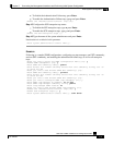
EXAMPLE #2:
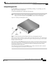
Following is a sample topology configuration for a non-redundant bump-in-the-wire (inline)
topology. In this topology, a single SCE 2000 is connected to one or two GBE links.
When the inline connection mode is specified, the user must specify the on-failure link behavior.
Would you like to enter the Topology configuration menu? [no]: y
Enter Connection mode:
1- inline
2- receive-only
Enter your choice [1]: 1
Is this a cascade deployment? [no]: no
Enter On-failure behavior:
1- bypass
2- cutoff
Enter your choice [1]: 1
Enter admin status of the SCE after abnormal boot:
1- Operational
2- Not-Operational
Enter your choice [1]: 1
Data collection for the system configuration is completed.
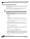
EXAMPLE #3:
Following is a sample topology configuration for a secondary SCE 2000 in a redundant inline
topology. In this topology there are two SCE 2000s that are cascaded via the cascade GBE ports
(ports 3 and 4). Each SCE 2000 is connected inline to both sides (subscribers/network) of one
GBE link.
In this case, the user must specify the physically-connected-link index (link-0 in our example), the
priority of the SCE 2000, and the on-failure link behavior.
Would you like to enter the Topology configuration menu? [no]: y
Enter Connection mode:
1- inline
2- receive-only
Enter your choice [1]: 1
Is this a cascade deployment? [no]: yes
Enter Physically connected link:
0- link-0
1- link-1
Enter your choice [0]: 0
Enter SCE 2000 priority:
1- primary
2- secondary
Enter your choice [1]: 2
Enter On-failure behavior:
1- bypass
2- cutoff
Enter your choice [1]: 1
Enter admin status of the SCE after abnormal boot:
1- Operational
2- Not-Operational
Enter your choice [1]: 1
Data collection for the system configuration is completed.