


Chapter 4 Installation and Maintenance
Preparing to Install the SCE 2000 Platform
SCE 2000 4xGBE Installation and Configuration Guide
OL-7824-02 4-3
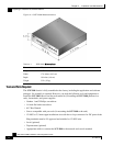
• Rack-mounting kit (optional)
• A new AC-input or DC-input power supply
• A new fan module
Site Requirement Guidelines
The environmental monitoring functionality in the SCE 2000 protects the system and components
from potential damage from over-voltage and over-temperature conditions. To ensure normal
operation and to avoid unnecessary maintenance, plan your site configuration and prepare your
site before installation. After installation, make sure the site maintains an ambient temperature of
41°F to 104°F (5°C to 40°C) with short term temperatures ranging from 23°F to 131°F (–5°C to
55°C), and keep the area around the SCE 2000 chassis free from dust.
Planning a proper location for the SCE 2000 and the layout of your equipment rack or wiring
closet is essential for successful system operation. Equipment placed too close together or
inadequately ventilated can cause system over-heating. In addition, chassis panels made
inaccessible by poor equipment placement can make system maintenance difficult.
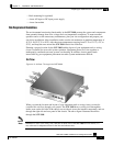
Airflow
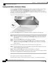
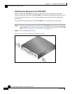
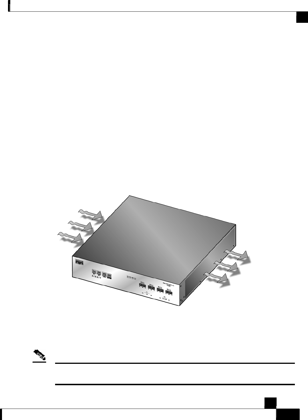
Figure 4-2: Airflow Through the SCE 2000
When you plan the location and layout of your equipment rack or wiring closet you need to
consider how air flows though your system. The SCE 2000 draws cooling air in through the
intake vents on the left side of the chassis, moves the air across the internal components, and out
through the right side and rear panel of the chassis. The above figure illustrates the airflow
through the SCE 2000.
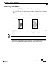
Note
Remember to leave a two inch (5 cm) clearance on both sides of the SCE 2000 and five inches (12.7
cm) at the rear for adequate airflow for the inlet and exhaust vents.