


Chapter 6 Cabling the Line Ports and Completing the Installation
Connecting the line ports to the network
SCE 2000 4xGBE Installation and Configuration Guide
OL-7824-02 6-3
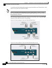
Single Link: Receive-only Topology
In this topology, an optical splitter resides physically on the GBE link that the SCE 2000 should
monitor. The optical splitter is connected to the SCE 2000 via Rx links only.
In this topology, the traffic passes through the optical splitter, which splits traffic to the SCE 2000.
Note
Receive-only topologies can also be implemented using a switch. Such a switch must support SPAN
functionality that includes separation between ingress and egress traffic and multiple SPAN-ports
destinations.
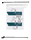
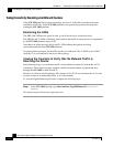
Figure 6-2: Cabling Diagram for Single SCE 2000 Single Link Receive-only Topology
The single link receive-only topology cabling is similar to that for single link inline, in that either
the first GBE link (first two ports) or the second GBE link (third and fourth ports) can be used, as
illustrated in the diagram above. The remaining pair of ports is unused.
Either port 1 or port 3 is used for connecting to the network element that is deployed on the
subscriber side of the SCE 2000 while port 2 or port 4 is used for connecting to the network
element that is deployed on the network side of the SCE 2000.
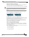
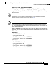
Dual Link: Single SCE 2000 Topologies
In this topology, one SCE 2000 is connected to two full duplex, GBE links. The SCE 2000 may
be either inline, to support both monitoring and traffic control functionality, or receive-only for
traffic monitoring functionality only.
When one SCE 2000 supports two links, the first two ports are connected to one link, while ports
3 and 4 are connected to the second link as follows;
• Port 1: Link 1, Subscriber side
• Port 2: Link 1, Network side
• Port 3: Link 2, Subscriber side
• Port 4: Link 2, Network side