


Chapter 2 Overview of the SCE 2000 Platform
SCE 2000 Installation Checklist
SCE 2000 4xGBE Installation and Configuration Guide
OL-7824-02 2-9
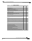
Table 2-5 SCE 2000 Installation Checklist
Task Verified
By
Date
Date SCE 2000 received
SCE 2000 and all accessories unpacked
Safety recommendations and guidelines reviewed
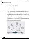
Topology verified: number of SCE 2000 platforms, number of links, and
whether inline or receive-only
Installation Checklist copied
Site log established and background information entered
Site power voltages verified
Site environmental specifications verified
Required passwords, IP addresses, device names, and so on, needed for
initial configuration available (refer to Setup Command Parameters (on
page 5-3))
Required tools available
Network connection equipment available
SCE 2000 mounted in rack (optional)
AC/DC power cables connected to AC/DC sources and SCE 2000 platform
Console port set for 9600 baud, 8 data bits, no parity, and 1 stop bit (9600
8N1)
ASCII terminal attached to console port
FE management port is operational
GBE line and cascade ports operational
Network interface cables and devices connected
System power turned on
System boot complete (SYSTEM–UP LED is on)
Correct hardware configuration displayed after system banner appears