


Chapter 4 Installation and Maintenance
Power Supply Overview
SCE 2000 4xGBE Installation and Configuration Guide
OL-7824-02 4-17
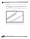
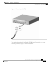
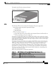
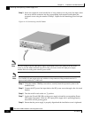
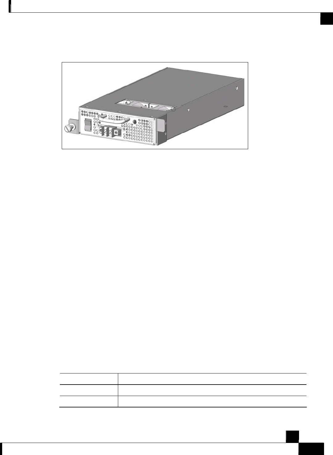
The handle of the DC unit is at the top of the unit.
Figure 4-13: DC Power Module
LEDs
The following LEDs are used to monitor the functioning of the power supply units:
• On the power supply unit (both AC-input and DC-input):
• IN LED (green)
• OK LED (green)
• On the Front Panel (on page 2-3):
• Power LED: There are two Power LEDs on the front panel (Power A and Power B), one
LED corresponding to each power supply unit
On both the AC-input and DC-input power supplies, the IN LED is used to monitor the voltages
received by the platform from the power source. If the input voltages are within normal operating
ranges, the green IN LED is illuminated. If the input voltages are above or below normal ranges,
the IN LED is not illuminated.
On both the AC-input and DC-input power supplies, the OK LED is used to monitor the power
supply DC output voltages used to power the platform. The normal operating ranges for the 12
VDC output voltage is between 11.9V and 12.1V. If the output voltages are within normal
operating ranges, the green OK LED is illuminated. If the 12 VDC output voltages are above
(more than 12.1V) or below (less than 11.9V) normal ranges, the OK LED is not illuminated.
The Power A and Power B LEDs on the front panel indicate whether the corresponding power
supply unit is functioning normally.
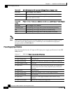
Refer to the following tables for LED status information
Table 4-4 IN LED Status for AC-input and DC-input Power Supply Units
LED State Power Supply Unit Condition
On (green) The input voltage is in the required range.
Off The input voltage is not in the required range.