Operation Manual
DBC Network Bridge
page 20
4 Operation
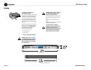
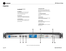
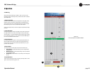
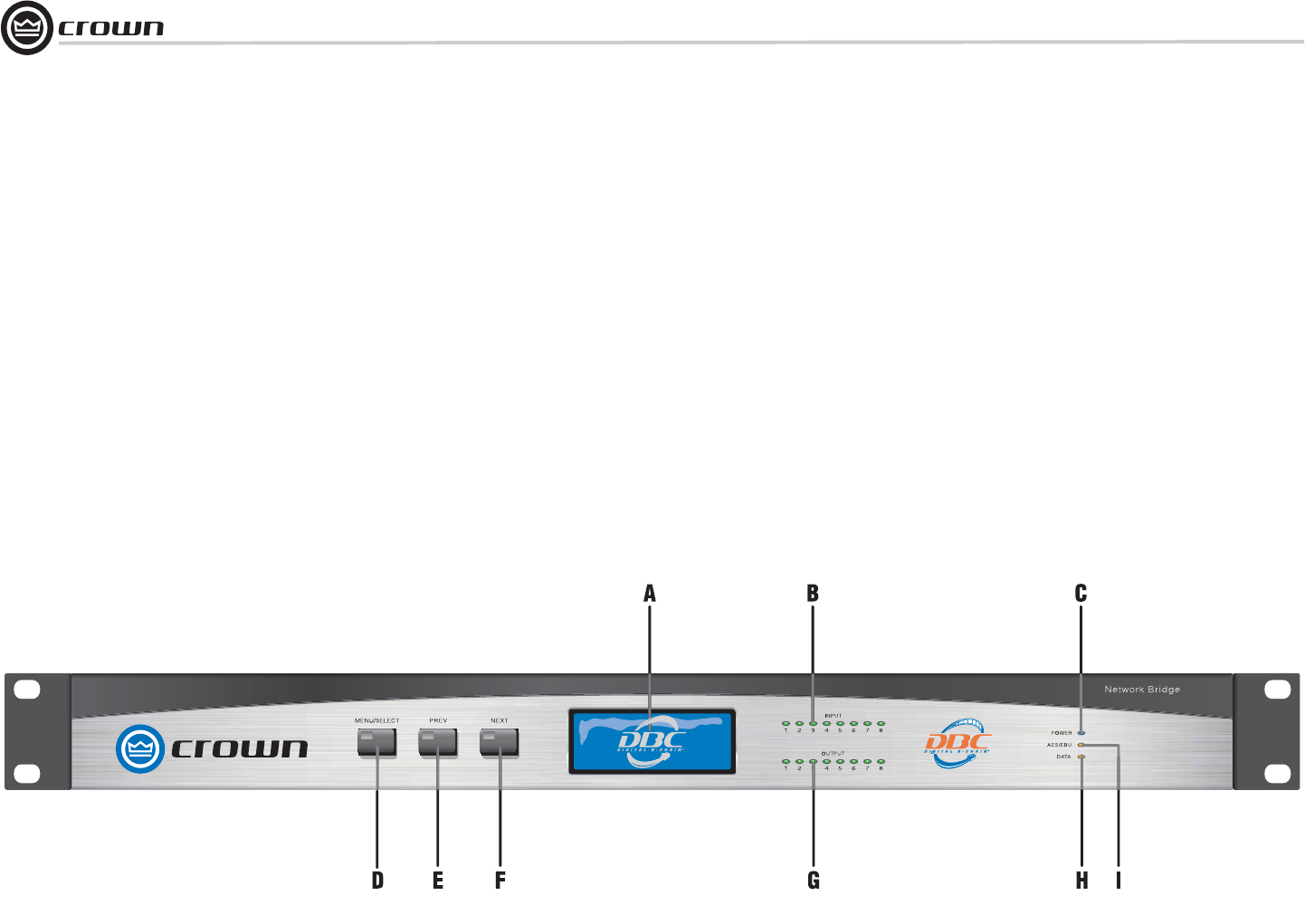
4.1 Front Panel Controls
and Indicators
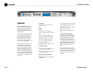
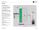
A. LCD Display
LCD digital display shows information about the
currently selected IQ address, inputs, presets,
scenes, and firmware information.
B. Input Display
An eight-segment LED display matrix shows input
signal presence for all eight analog or digital inputs.
C. Power Indicator
Blue LED shows that the unit is plugged in and AC
power is being supplied. The unit does not have a
power on/off switch.
D. Menu/Select Button
Scrolls through the menus of IQ address, inputs,
presets, scenes, and firmware information. Also
used to select a parameter that is found by the Next/
Prev buttons.
E., F. Next/Previous Buttons
These two buttons scroll through parameters in
each menu.
G. Output display
An eight-segment LED display matrix shows output
signals for all eight surround channels.
H. Data Indicator
Amber LED flashes when commands addressed to
the DBC Bridge are received.
I. AES/EBU Indicator
Amber LED illuminates when the unit is switched to
AES digital inputs.
Figure 4.1 Front Panel Controls and Indicators


