Operation Manual
DBC Network Bridge
page 28
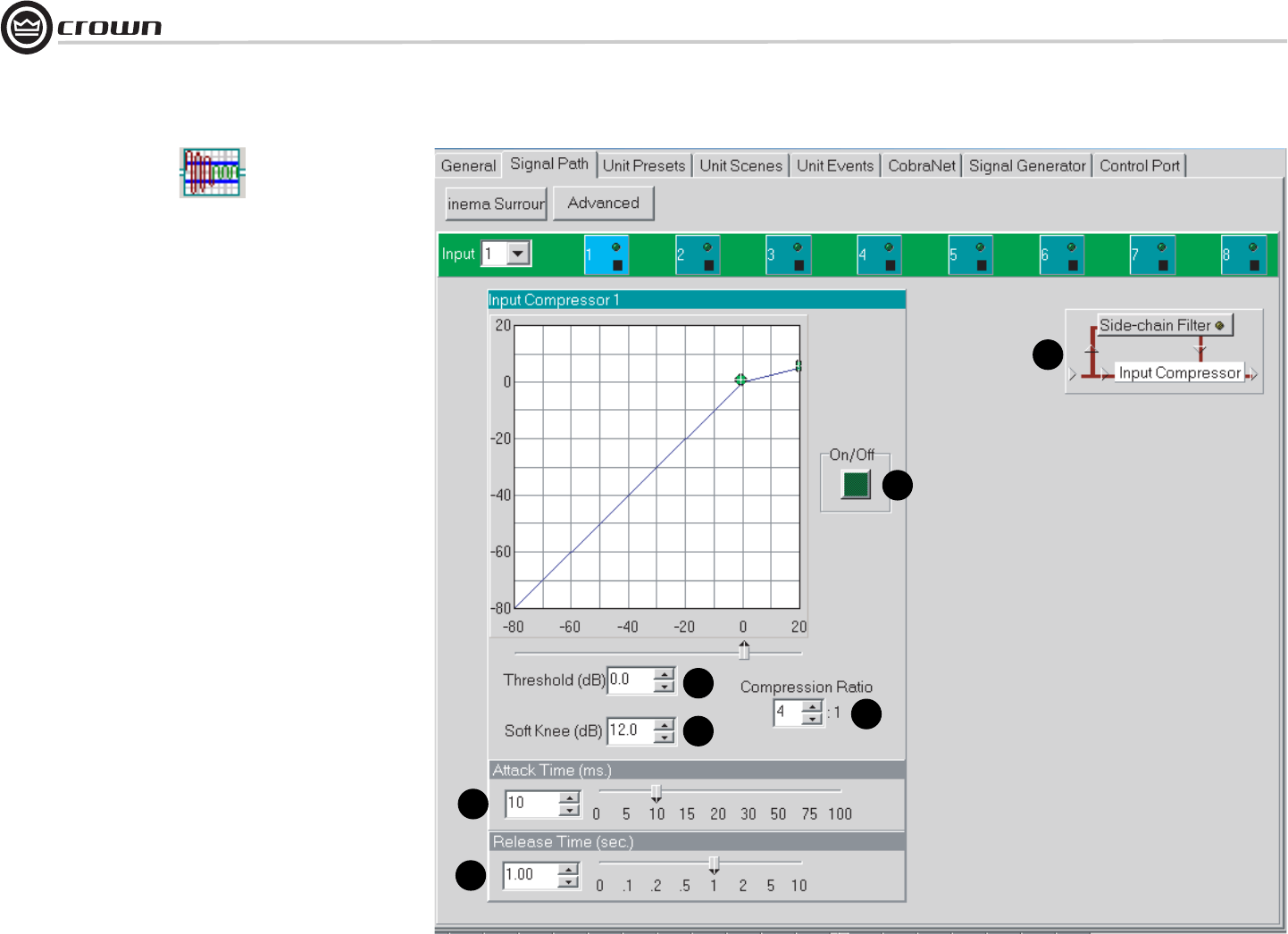
4.7.2 Input Compressor
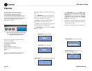
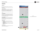
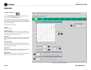
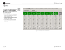
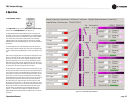
To open the Input Compressor window (Figure 4.8), select its icon (shown
above) in any channel in the Signal Path window.
The input compressor provides a means for controlling the dynamic range of
input signals. It is a feed-forward type, which performs the compression after the
Input Level Meter. The Input Compressor’s effect on input gain is metered by the
Input Dynamic Cut/Boost Meter.
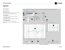
Seven parameters control this feature:
1. On/Off
Turns this feature on or off.
2. Compression Ratio
Determines how many dB the input level must change for a 1 dB change in out-
put level. Dynamic variations in the input signal will be reduced by a factor equal
to the compression ratio. Control range is 2:1 to 32:1.
3. Threshold
Specifies the average signal level (after side-chain processing) above which the
compressor will begin to reduce gain. Control range is from –80 to +20dB in 1
dB steps.
4. Soft Knee (Width)
Sets a range in dB around the actual threshold through which the compressor
gain is gradually modified from unity to the final compressed gain. Control range
is from 0 dB to +20 dB in 0.5 dB steps.
5. Attack Time
Sets the time required for the Compressor to decrease its gain by 20 dB. Control
range is from 1.0 to 100 milliseconds in 1 millisecond increments.
6. Release Time
Sets the time required for the Compressor to increase its gain by 20 dB. Control
range is from 0.1 to 10 seconds in 10 millisecond increments.
4 Operation
1
2
3
4
5
6
7
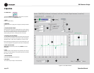
Figure 4.8 Input Compressor Window


