DBC Network Bridge
Operation Manual page 65
5.3.7 Output Path
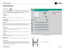
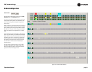
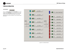
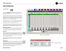
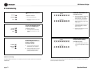
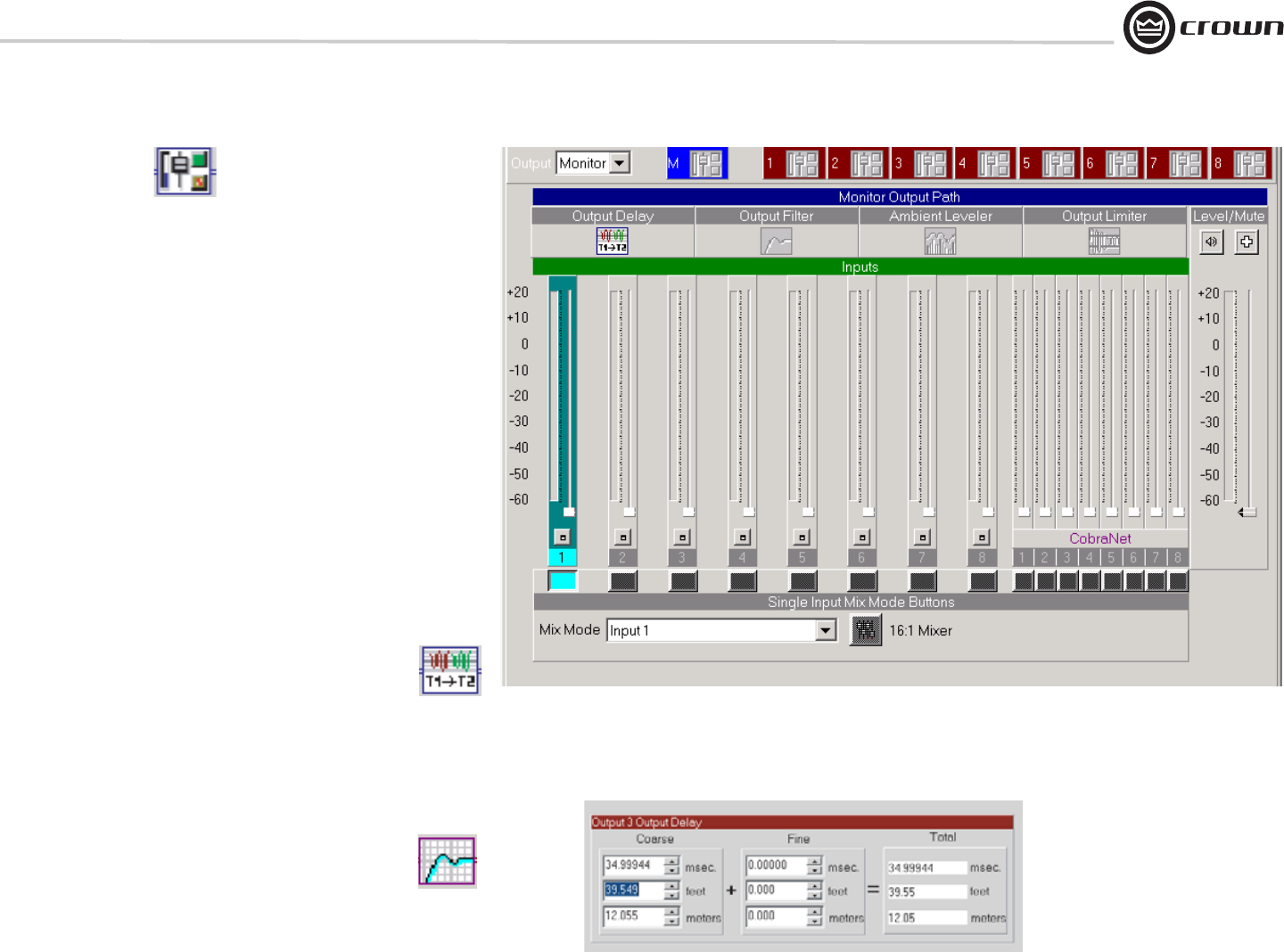
Starting in the Signal Path window, at the end of the Output processing section,
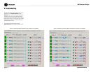
you can access the Output Path window (Figure 5.28) by clicking on its icon
(shown above).
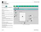
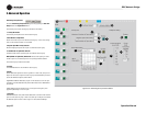
In addition to the output of each of the sixteen Input Processing Sections, the eight
CobraNet Inputs are fed to the Matrix Mixer, providing a 24 Input by 10 Output fully
independent crosspoint mix as controlled by the Input/Output Matrix. Each of the ten
Output Processing Sections has independent fader control of all of the inputs to the
selected output, i.e. a 24:1 mixer, as shown in Figure 5.29.
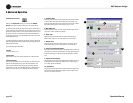
The Mix Mode drop-down box is used for selecting exclusive assignments between
a particular input and output. This function is repeated with the Single Input Mix
Mode Buttons or the routing can be reassigned to the 24:1 mixer.
The selected output channel displays the status of the Output Processing Section
objects and their parameters can be accessed by clicking on these icons. There is
also a button to quickly access the Input/Output Matrix for further routing options.
Output Processing Sections
Each of the ten Outputs, (two 'Main' and eight 'AUX)', have independent Output Pro-
cessing Sections to allow control of the mixed output. Output Processing functions
include delay, filters, ambient leveler, limiter, fader, mute, and polarity inverter.
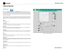
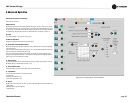
Output Delay
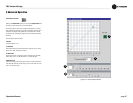
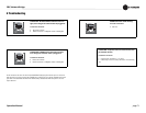
Output Delay (Figure 5.29) can be set for each Output Processing Section. This sig-
nal delay is especially useful in loudspeaker array alignment, where the crossovers,
mix, and other processing is complete and the loudspeaker needs to be aligned to
the system.The inherent delays of the various input signals should be corrected by
the delay in the Input Processing Section.
Delay is displayed by IQwic software in milliseconds, feet, and meters. Available
delay for each Output Processing Section is up to 2 seconds in 20 microsecond
steps (1/4 inch).
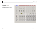
Output EQ Filters
These filters are identical to the Input EQ Filters. Please read Section 4.7.4 on Input
EQ Filters for more information. As was the case with the Input EQ Filters, the two
DSP’s that process the outputs have a finite amount of processing capability. Each of
the DSP’s can provide up to 64 filters, with Main 1 and AUX 1-4 processed by one
DSP and Main 2 and AUX 5-8 processed by the other. The CPU Utilization meters
indicate how much DSP processing capability remains.
5 Advanced Operation
Figure 5.29 Output Delay Window
Figure 5.28 Output Path Window


