DBC Network Bridge
Operation Manual page 43
4.8 General Firmware Features
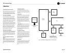
Note: The following features are accessed via IQwic
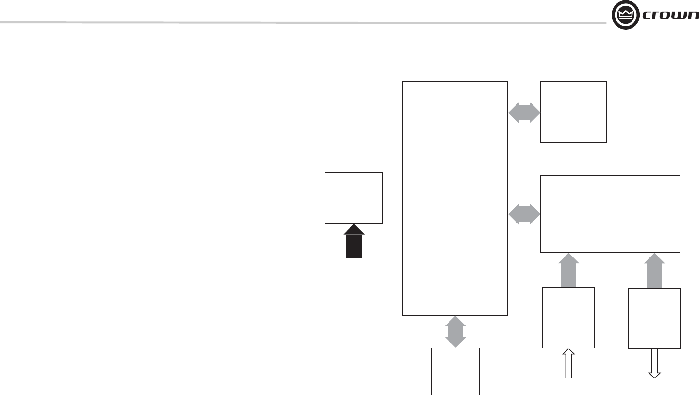
software unless otherwise stated. Refer to Figure
4.24, DBC Network Bridge Signal Flow Block Dia-
gram for feature locations in the audio signal chain.
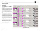
4.8.1 Input Level Meters
Audio level peak program meters are provided for
each input. The meters sense the audio signal
immediately after analog to digital conversion, and
respond with 1.7 millisecond attack and 350 milli-
second release. Meter range is from –60 to +20 dBu
with 0.5 dB resolution. Calibration is in dBu when
the input is in “line” mode and set at 0 dB.
4.8.2 Input Dynamic Cut/Boost Meters
Meters are provided for each Input A/B Processing
Section to indicate the overall cut or boost being
applied from all signal processing features that
affect input gain, including Auto-Leveler, Input
Compressor, and Auto-Mixing. Meter range is from
–60 to +20 dBu with 0.5 dB resolution.
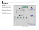
4.8.3 Output Level Meters
Audio level meters are provided for each output. The
meters sense the audio signal immediately after the
audio output processing block, and respond with
1.7-millisecond attack and 350-millisecond release.
Meter range is from –60 to +20 dBu with 0.5 dB
resolution.
4.8.4 Output Dynamic Cut/Boost
Meters
Meters are provided for each output to indicate the
overall cut or boost being applied from all signal
processing features that affect output gain, includ-
ing Ambient-Leveler and Output Limiter. Meter
range is from –60 to +20 dBu with 0.5 dB resolu-
tion.
4 Operation
Power Supply
System
Control
Control
Port
Front
Display
DSP
Audio
Input
Audio
Output
8 Digital DB25 inputs
8 Analog DB25 inputs
2 Auxiliary analog inputs
CobraNet
100 VAC - 240 VAC
50/60 Hz
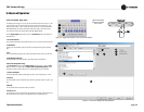
Figure 4.24 DBC Network Bridge Signal Flow Block Diagram
4.8.5 Memory Backup
The DBC Network Bridge settings are stored in
high-endurance flash memory whenever a parame-
ter is changed. Changed settings are updated every
few seconds.
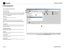
4.8.6 Presets
The parameters for all functions in the DBC Network
Bridge can be saved as presets and each can be
given a unique 32-character name. A total of 32
user presets can be stored in the DBC Network
Bridge’s flash memory. Presets can be recalled via
the front-panel selector buttons, IQ for Windows
preset selector controls, from within events, or by
an external system controller via the Multi-Function
Control Port.
• Preset Segue: When a preset is selected, the
Preset Segue feature provides a smooth transition to
the new preset. Preset Segue can be set to either a
fixed time in seconds or a fixed rate in dB per sec-
ond. Range for fixed time in seconds is 1 to 255
seconds. Range for fixed rate in dB per second is
from 0.5 dB to 40 dB.
4.8.7 Real Time Clock
The onboard Real Time Clock tracks day, date, hour,
minute and second, and may be set to any date and
time desired, or to match that of the computer run-
ning IQ for Windows software. The clock is used as
a time reference for the Events Scheduling feature.
Internal capacitor storage allows the clock to run for
up to 45 days without power being applied to the
DBC Network Bridge.
4.8.8 Events
User presets can be scheduled for recall as an Event
at a specific date and time, and also can be set to
repeat. A total of 32 Events can be scheduled, and
each Event can be given a unique 32-character
name.


