


NOTE: You must remove the system board to replace a faulty system board.
1. Ensure that you read the Safety instructions.
2. Follow the procedure listed in Before working inside your system.
3. Keep the 5 mm and 6 mm Hex nut drivers, #2 Phillips screwdriver, and #2 Phillips round screwdriver
ready.
4. Remove the following:
a. processor(s) and heat sink(s)
b. memory modules
c. cooling shroud
d. hard drives/SSDs
e. hard drive/SSD backplane
f. hard drive/SSD cage
g. storage controller card
h. expander card
i. PCIe mezzanine cards
j. IDSDM/rSPI card
k. NDC
l. SD vFlash card
m. internal USB key
5. Install an I/O connector cover on the I/O connector(s) at the back of the board.
CAUTION: Do not lift the system board by holding a memory module, processor, or other
components.
CAUTION: Temporarily label the hard drive/SSD before removal so that you can replace them in
their original locations.
WARNING: The processor and heat sink can become extremely hot. Be sure the processor has
had sufficient time to cool before handling.
WARNING: The memory modules are hot to touch for some time after the system has been
powered down. Allow time for the memory modules to cool before handling them. Handle the
memory modules by the card edges and avoid touching the components.
Steps
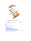
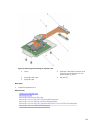
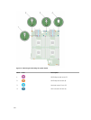
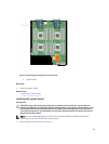
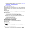
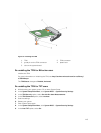
1. Remove the screws on the system board that secure the system board to the chassis.
2. Lift the system board by its edges and orient it upward.
3. Remove the system board from the chassis by disengaging the USB connectors from the slots on the
front wall of the chassis.
4. Ensure that the I/O connector cover is still in place on the I/O connector at the back of the system
board.
109