


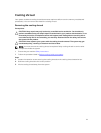

1. Ensure that you read the Safety instructions.
2. Follow the procedure listed in Before working inside your system.
3. If installed, remove the heat sink and the processor.
4. Ensure that the memory module socket ejectors are in the open position.
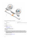
Steps
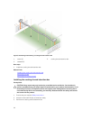
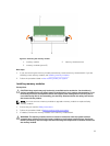
1. Align the processor blank and DIMM blank with the memory module sockets on the system board.
2. Lower the processor blank and DIMM blank onto the memory module sockets such that the bottom
edges of the blank is firmly inserted into the memory module sockets.
3. Press the blank firmly until the memory module socket ejectors click into place.
Next steps
1. Follow the procedure listed in After working inside your system.
Related Links
Removing a heat sink
Removing a processor
System memory
Your system supports DDR4 registered DIMMs (RDIMMs) and load reduced DIMMs (LRDIMMs). It supports
DDR4 voltage specifications.
NOTE: MT/s indicates DIMM speed in MegaTransfers per second.
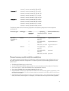
Memory bus operating frequency can be either 1333 MT/s, 1600 MT/s, 1866 MT/s, or 2133 MT/s
depending on the:
• DIMM type (RDIMM or LRDIMM)
• DIMM configuration (number of ranks)
• Maximum frequency of the DIMMs
• Number of DIMMs populated per channel
• System profile selected (for example, Performance Optimized, Custom, or Dense Configuration
Optimized)
• Maximum supported DIMM frequency of the processors
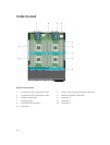
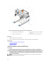
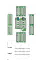
Your system contains 48 memory sockets split into four sets of 12 sockets, one set per processor. Each
12-socket set is organized into four channels. In each channel, the release levers of the first socket are
marked white, the second socket black, and the third socket green.
NOTE: DIMMs in sockets A1 to A12 are assigned to processor 1, B1 to B12 to processor 2, C1 to C12
to processor 3, and D1 to D12 to processor 4.
47