


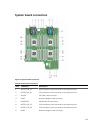
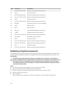

Item Connector Description
9 B1, B2, B5, B6, B9, B10 Memory module sockets (processor 2)
10 CPU2 Processor socket 2
11 B3, B4, B7, B8, B11, B12 Memory module sockets (processor 2)
12 C3, C4, C7, C8, C11, C12 Memory module sockets (processor 3)
13 CPU3 Processor socket 3
14 C1, C2, C5, C6, C9, C10 Memory module sockets (processor 3)
15 BATTERY Connector for the 3.0 V coin cell battery
16 USB2 USB connector
17 USB1 USB connector
18 SATA_BP Hard-drive/SSD backplane connector
19 J_PERC Storage controller card connector
20 D3, D4, D7, D8, D11, D12 Memory module sockets (processor 4)
21 J_BP_PWR Backplane power connector
22 CPU4 Processor socket 4
23 D1, D2, D5, D6, D9, D10 Memory module sockets (processor 4)
24 A1, A2, A5, A6, A9, A10 Memory module sockets (processor 1)
25 CPU1 Processor socket 1
26 A3, A4, A7, A8, A11, A12 Memory module sockets (processor 1)
Disabling a forgotten password
The software security features of sled include a system password and a setup password. The password
jumper enables these password features or disables them, and clears any password(s) currently in use.
Prerequisites
CAUTION: Many repairs may only be done by a certified service technician. You should only
perform troubleshooting and simple repairs as authorized in your product documentation, or as
directed by the online or telephone service and support team. Damage due to servicing that is
not authorized by Dell is not covered by your warranty. Read and follow the safety instructions
that came with the product.
Steps
1. Turn off the sled using the operating system commands or the CMC.
2. Remove the sled from the enclosure to access the jumpers.
3. Move the jumper on the system-board jumper from pins 2 and 3 to pins 1 and 2.
4. Install the sled in the enclosure.
5. Turn on the sled.
When the sled is on, the power-on indicator is solid green. Allow the sled to finish booting.
126