


IM584000300 Installation Instructions
Issue AB, April 3, 2013 Spec. No. 584000300 (Model 4015-X003)
Page 8 Chapter 2. Installing the System
This document is property of Emerson Network Power, Energy Systems, North America, Inc. and contains confidential and proprietary information owned by Emerson Network Power, Energy
Systems, North America, Inc. Any copying, use, or disclosure of it without the written permission of Emerson Network Power, Energy Systems, North America, Inc. is strictly prohibited.
CHAPTER 2.
INSTALLING THE SYSTEM
The individual components of the DC Power System may be shipped as a complete
solution factory installed and wired in an IT rack, or may be shipped separately to be
installed in a customer provided IT rack.
GENERAL REQUIREMENTS
This product is intended only for installation in a restricted access location on or
above a non-combustible surface.
Front and rear access is required for installation.
Required minimum spacing from the rear of the power and control sub-rack to a wall
or other solid surface is thirty-six (36) inches for proper ventilation of system
components. Required minimum spacing from the rear of the load distribution sub-
rack to a wall or other solid surface is twelve (12) inches for proper ventilation of
system components.
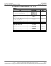
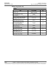
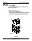
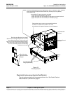
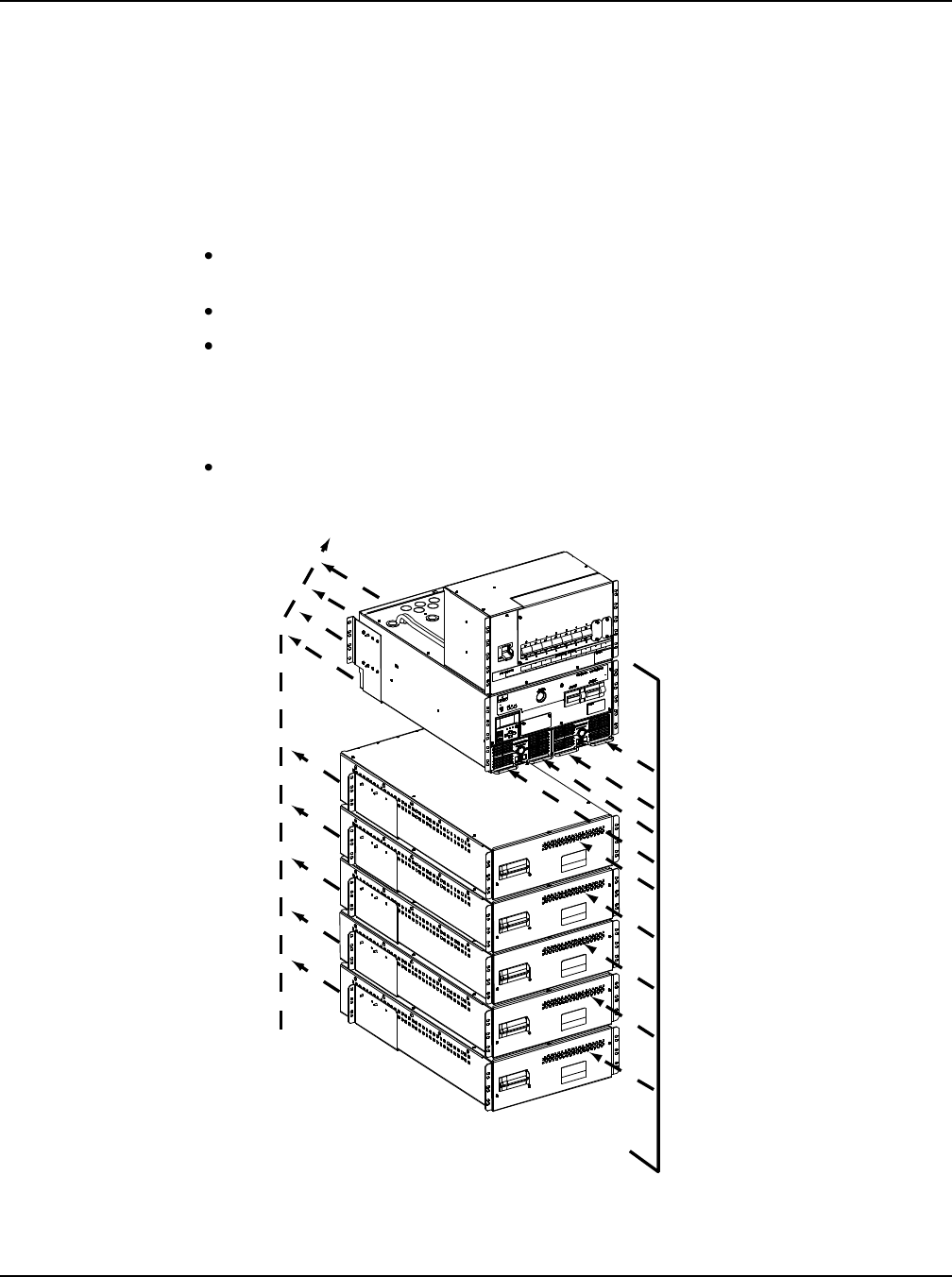
See Figure 2-1 for an air flow diagram.
Figure 2-1
Air Flow Diagram
Front
Notes:
1. Do not block
air intake openings.
Air Flow
Cold Aisle
Hot Aisle