


IM584000300 Installation Instructions
Issue AB, April 3, 2013 Spec. No. 584000300 (Model 4015-X003)
Page 36 Chapter 3. Making Electrical Connections
This document is property of Emerson Network Power, Energy Systems, North America, Inc. and contains confidential and proprietary information owned by Emerson Network Power, Energy
Systems, North America, Inc. Any copying, use, or disclosure of it without the written permission of Emerson Network Power, Energy Systems, North America, Inc. is strictly prohibited.
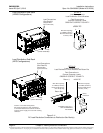
Temperature Probes
Note: Each temperature probe consists of two pieces that plug together to make a
complete probe. See SAG584000300 for part numbers and descriptions.
Up to two (2) temperature probes can be connected to the IB2. Any combination of the
two (2) temperature probes can be programmed to monitor ambient air temperature
and/or battery temperature. A temperature probe set to monitor battery temperature can
also be used for the rectifier battery charge temperature compensation feature. The
battery charge temperature compensation feature allows the controller to automatically
increase or decrease the output voltage of the system to maintain battery float current as
battery temperature decreases or increases, respectively. Battery life can be extended
when an optimum charge voltage to the battery with respect to temperature is
maintained. A temperature probe set to monitor battery temperature can also be used for
the BTRM (battery thermal runaway management) feature. The BTRM feature lowers
output voltage when a high temperature condition exist to control against battery thermal
runaway. Refer to the ACU+ Controller Operation Instructions (UM1M820NNB-1) for
programming information.
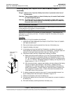
A temperature probe programmed to monitor battery temperature should be mounted on
the top or side of a battery block to sense battery temperature. A temperature probe used
for battery charge temperature compensation and/or BTRM (Battery Thermal Runaway
Management) should also be mounted on the top or side of a battery block. A
temperature probe programmed to monitor ambient temperature should be mounted in a
convenient location, away from direct sources of heat or cold.
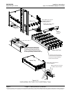
Recommended Battery Temperature Probe Location for Furnished List 91, 92
Battery Tray: If a battery temperature probe is to be used, it is recommended to
secure it on top of a battery block near the location indicated in Figure 3-12.
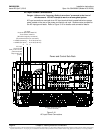
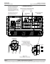
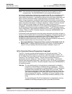
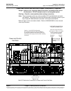
ACU+ Controller Ethernet Connection (if required)
The ACU+ Controller provides a Web Interface via an Ethernet connection. This
interface can be accessed locally on a computer or remotely through a network. An
RJ-45 10BaseT jack is provided on the front of the ACU+ Controller for connection to a
computer or into a customer's network. This jack has a standard Ethernet pin
configuration scheme, twisted pair. Refer to Figure 3-14 for location. Use shielded
Ethernet cable (grounded at both ends). Note that the ACU+ RJ-45 jack is connected to
chassis ground. Refer to the ACU+ Controller Operation Instructions (UM1M820NNB-1)
for operational details.
Warning: The intra-building port(s) of the equipment or subassembly is suitable for
connection to intra-building or unexposed wiring or cabling only. The intra-
building port(s) of the equipment or subassembly MUST NOT be metallically
connected to the interfaces that connect to the OSP or its wiring. These
interfaces are designed for use as intra-building interfaces only (Type 2 or
Type 4 ports as described in GR-1089-CORE, Issue 4) and require isolation
from the exposed OSP cabling. The addition of Primary Protectors is not
sufficient protection in order to connect these interfaces metallically to OSP
wiring.
The intra-building port (RJ-45) of the equipment or subassembly must use
shielded intra-building cabling/wiring that is grounded at both ends.