


Installation Instructions IM584000300
Spec. No. 584000300 (Model 4015-X003) Issue AB, April 3, 2013
Chapter 4. Installing the Rectifier Module Page 41
This document is property of Emerson Network Power, Energy Systems, North America, Inc. and contains confidential and proprietary information owned by Emerson Network Power, Energy
Systems, North America, Inc. Any copying, use, or disclosure of it without the written permission of Emerson Network Power, Energy Systems, North America, Inc. is strictly prohibited.
CHAPTER 4.
INSTALLING THE RECTIFIER MODULE
The rectifier module is hot swappable. It can be installed with the system operating if
these instructions are carefully followed.
Note: There is a two step insertion process.
Procedure
1) Unpack the rectifier module.
2) Open the respective rectifier module’s AC input circuit breaker on the front of the
power and control sub-rack.
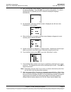
3) Place the “Latch Release” located on the front of the rectifier module to the LEFT
position. See Figure 4-1.
4) Place the rectifier module into an unoccupied mounting slot without sliding it in
completely. Gently push the rectifier module into the mounting slot until it stops.
Note that the rectifier module will NOT be completely seated in the mounting slot
until the next step is performed.
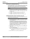
5) Live Systems: Wait for the green power indicator to illuminate. Ensuring the
green power indicator stays on, slide the “Latch Release” located on the front of
the rectifier module to the RIGHT position. Gently push the rectifier module into
the mounting slot until it is completely seated.
De-energized Systems: Slide the “Latch Release” located on the front of the
rectifier module to the RIGHT position. Gently push the rectifier module into the
mounting slot until it is completely seated.
6) Secure the rectifier module to the power and control sub-rack by tightening the
retaining screw.
7) Repeat the above steps for each rectifier module being installed in the system.
8) After the rectifier modules are physically installed in their mounting slots, they are
ready for operation immediately after power is supplied to them.
9) Close the respective rectifier module’s AC input circuit breaker on the front of the
power and control sub-rack.
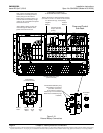
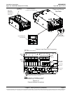
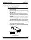
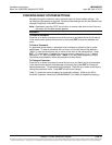
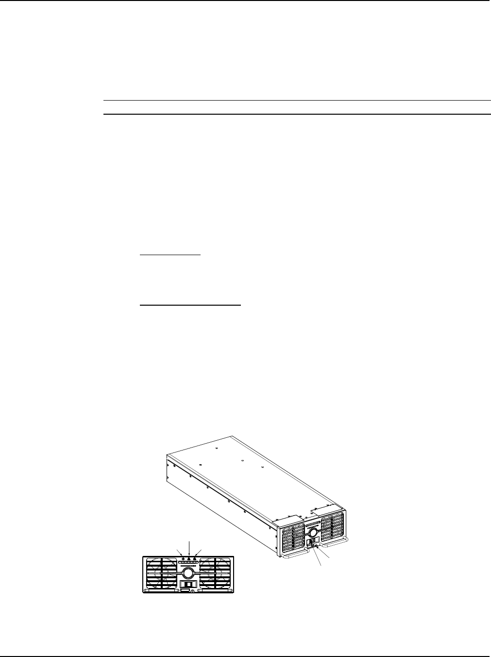
Figure 4-1
Installing a Rectifier Module
Latch Release
Retaining Screw
Power Indicator (Green)
Protection Indicator (Yellow)
Alarm Indicator (Red)
Front View