Installation Instructions IM584000300
Spec. No. 584000300 (Model 4015-X003) Issue AB, April 3, 2013
Chapter 3. Making Electrical Connections Page 15
This document is property of Emerson Network Power, Energy Systems, North America, Inc. and contains confidential and proprietary information owned by Emerson Network Power, Energy
Systems, North America, Inc. Any copying, use, or disclosure of it without the written permission of Emerson Network Power, Energy Systems, North America, Inc. is strictly prohibited.
When System Components are Furnished Loose to be Installed in a
Customer Furnished IT Rack
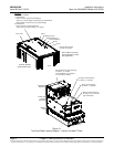
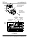
If the system components are furnished loose to be installed in a customer furnished IT
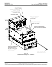
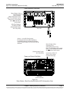
rack, the following connections are required. Refer to Figure 3-2 for a cable routing
diagram.
Grounding Connections between the Sub-Racks and the IT Rack Ground Bar (page
17)
Return Bar Grounding Connection (NPG Configurations Only) (page 17)
HRMG Grounding Connection (HRMG Configurations Only) (page 17)
Sub-Racks Electrical Interconnections (page 21)
Site Ground to IT Rack Ground Bar (page 25)
AC Input Connections (page 28)
DC Load Distribution Connections to List 21-24 Distribution Sub-Rack(s) (page 29)
Battery Sub-Trays Installed in List 91-92 Battery Tray(s) (page 31)
External Batteries (if required) (page 33)
IB2 (ACU+ Controller Interface Board) Connections (if required) (page 35)
ACU+ Controller Ethernet Connection (if required) (page 36)
Power and Control Sub-Rack Bulk Output Connections (if required) (page 40)


