


IM584000300 Installation Instructions
Issue AB, April 3, 2013 Spec. No. 584000300 (Model 4015-X003)
Page 42 Chapter 5. Initially Starting the System
This document is property of Emerson Network Power, Energy Systems, North America, Inc. and contains confidential and proprietary information owned by Emerson Network Power, Energy
Systems, North America, Inc. Any copying, use, or disclosure of it without the written permission of Emerson Network Power, Energy Systems, North America, Inc. is strictly prohibited.
CHAPTER 5.
INITIALLY STARTING THE SYSTEM
Caution: Performing various steps in the following procedures may cause a
service interruption and/or result in the extension of alarms. Notify any
appropriate personnel before starting these procedures. Also, notify
personnel when these procedures are completed.
Note: Contact Emerson sales for startup assistance.
INITIAL STARTUP PREPARATION
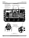
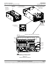
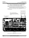
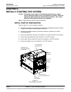
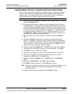
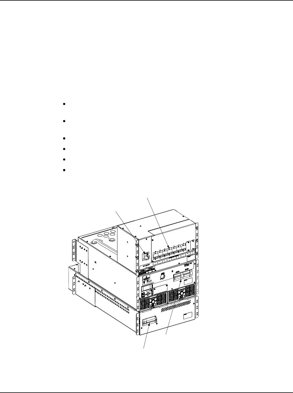
Refer to Figure 5-1 for circuit breaker locations.
Ensure that all blocks in the appropriate “Installation Acceptance Checklist” starting
on page 6 have been checked (except the last one).
Ensure that a rectifier module or a blank cover panel is installed in all rectifier
mounting positions.
Ensure the distribution row input circuit breaker is in the OFF position (if furnished).
Ensure each load distribution circuit breaker is in the OFF position.
Ensure each rectifier module AC input circuit breaker is in the OFF position.
Ensure each battery tray circuit breaker is in the OFF position.
Figure 5-1
Circuit Breaker Locations
Front
Rectifier Module
AC Input Circuit Breakers
Distribution Row
Input Circuit Breaker
(if furnished)
Load Distribution
Circuit Breakers
Battery Tray
Circuit Breaker
Load
Distribution
Sub-Rack
Power and
Control
Sub-Rack
Battery
Tray