


Installation Instructions IM584000300
Spec. No. 584000300 (Model 4015-X003) Issue AB, April 3, 2013
Chapter 3. Making Electrical Connections Page 31
This document is property of Emerson Network Power, Energy Systems, North America, Inc. and contains confidential and proprietary information owned by Emerson Network Power, Energy
Systems, North America, Inc. Any copying, use, or disclosure of it without the written permission of Emerson Network Power, Energy Systems, North America, Inc. is strictly prohibited.
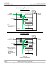
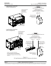
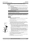
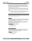
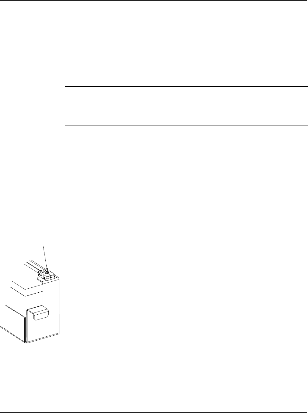
Battery Sub-Tray
Connector
Red +
Black -
Installing Battery Sub-Trays in List 91 and 92 Battery Tray(s) (if
furnished)
Danger: Adhere to the “Important Safety Instructions” presented at the front of
this document.
Warning: Ensure battery breaker on front of battery tray is turned off and locked-
out before beginning work.
Warning: The battery tray is pre-wired with output battery cables with exposed
ends. DO NOT install batteries into a battery tray that is not wired into
the power and control sub-rack.
Battery Manufacturer Information
Refer to System Application Guide SAG584000300 for specifications and manufacturers
of the batteries to be installed in this power system.
Installing Battery Sub-Trays
Batteries are furnished with this system but shipped separately. These batteries are
packaged in six (6) battery sub-trays. All battery wiring within the battery sub-trays are
done at the factory.
Procedure
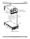
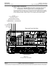
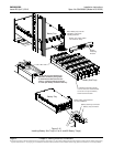
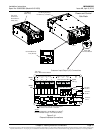
Refer to Figure 3-12 as this procedure is performed.
1) ENSURE BATTERY BREAKER ON FRONT OF BATTERY TRAY IS TURNED
OFF AND LOCKED-OUT.
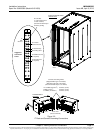
2) Remove the battery retaining bracket from the rear of the battery tray.
3) Unpack the battery sub-trays.
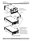
4) In the battery sub-trays that hold five (5) batteries, one battery string cable is
disconnected and sleeved at the factory for transportation. Locate this lead and
connect it to the open battery terminal in that tray. See Figure 3-12.
5) Check each battery sub-tray voltage before installing as follows.
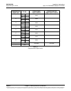
a) Battery sub-trays contain either four (4) or five (5) pre-wired battery blocks.
Note that the minimum acceptable voltage of a single battery block is 11.5V
DC. So, acceptable voltage of a battery sub-tray with four (4) battery blocks
is 11.5V x 4 = 46V DC. Acceptable voltage of a battery sub-tray with five (5)
battery blocks is 11.5V x 5 = 57.5V DC.
b) With an external meter, measure each battery sub-tray voltage at the battery
sub-tray connector (see illustration in left margin). If battery sub-tray
voltages are OK, install each battery sub-tray as detailed in the remaining
steps of this procedure. Contact Emerson Technical Support if battery sub-
tray voltages are not within limits. Contact information is provided on the
inside back cover of this document.
6) If a battery temperature probe is to be used, it is recommended to secure it on
top of a battery block near the location indicated in Figure 3-12.
7) Slide pre-wired battery sub-trays into battery tray.
8) Connect each battery sub-tray connector to the respective connector located on
the battery tray.
9) Re-install the battery retaining bracket to the battery tray.