


Installation Instructions IM584000300
Spec. No. 584000300 (Model 4015-X003) Issue AB, April 3, 2013
Chapter 3. Making Electrical Connections Page 13
This document is property of Emerson Network Power, Energy Systems, North America, Inc. and contains confidential and proprietary information owned by Emerson Network Power, Energy
Systems, North America, Inc. Any copying, use, or disclosure of it without the written permission of Emerson Network Power, Energy Systems, North America, Inc. is strictly prohibited.
CHAPTER 3.
MAKING ELECTRICAL CONNECTIONS
IMPORTANT SAFETY INSTRUCTIONS
Danger: Adhere to the “Important Safety Instructions” presented at the front of
this document.
WIRING CONSIDERATIONS
All AC input and 400V DC output wiring, branch circuit protection, and grounding should
follow the current edition of the American National Standards Institute (ANSI) approved
National Fire Protection Association's (NFPA) National Electrical Code (NEC), and
applicable local codes. For operation in countries where the NEC is not recognized,
follow applicable codes.
For wire size, branch circuit protection, crimp lug, and general wiring
recommendations; refer to System Application Guide SAG584000300.
TORQUE
Torque all connections as specified in the illustrations presented in this chapter.
OUTPUT GROUND CONFIGURATIONS
These instructions apply both to the High Resistance Midpoint Grounded (HRMG) and
Negative Pole Grounded (NPG) configurations. Ensure you follow the proper procedures
for the configuration you have. Refer to the part number on your equipment. The table
on the front cover of this document lists the various equipment part numbers and the
configuration they apply to.
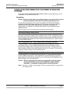
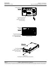
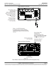
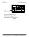
CABLE ROUTING
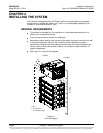
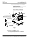
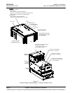
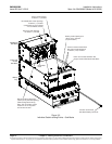
When System is Furnished in a Factory Provided IT Rack (List R1, R2)
If the system is furnished in a factory provided IT rack, connections between the system’s
sub-racks and also to the IT rack ground bar are factory made. The electrical
connections the customer is required to make are the following. Refer to Figure 3-1 on
the next page for a cable routing diagram.
Site Ground to IT Rack Ground Bar (page 25)
AC Input Connections (page 28)
DC Load Distribution Connections to List 21-24 Distribution Sub-Rack(s) (page 29)
Battery Sub-Trays Installed in List 91-92 Battery Tray(s) (page 31)
External Batteries (if required) (page 33)
IB2 (ACU+ Controller Interface Board) Connections (if required) (page 35)
ACU+ Controller Ethernet Connection (if required) (page 36)
Power and Control Sub-Rack Bulk Output Connections (if required) (page 40)
GO TO PAGE 25 FOR THE ELECTRICAL CONNECTIONS PROCEDURES.