


Installation Instructions IM584000300
Spec. No. 584000300 (Model 4015-X003) Issue AB, April 3, 2013
Chapter 3. Making Electrical Connections Page 19
This document is property of Emerson Network Power, Energy Systems, North America, Inc. and contains confidential and proprietary information owned by Emerson Network Power, Energy
Systems, North America, Inc. Any copying, use, or disclosure of it without the written permission of Emerson Network Power, Energy Systems, North America, Inc. is strictly prohibited.
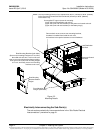
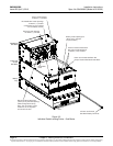
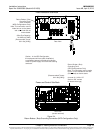
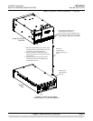
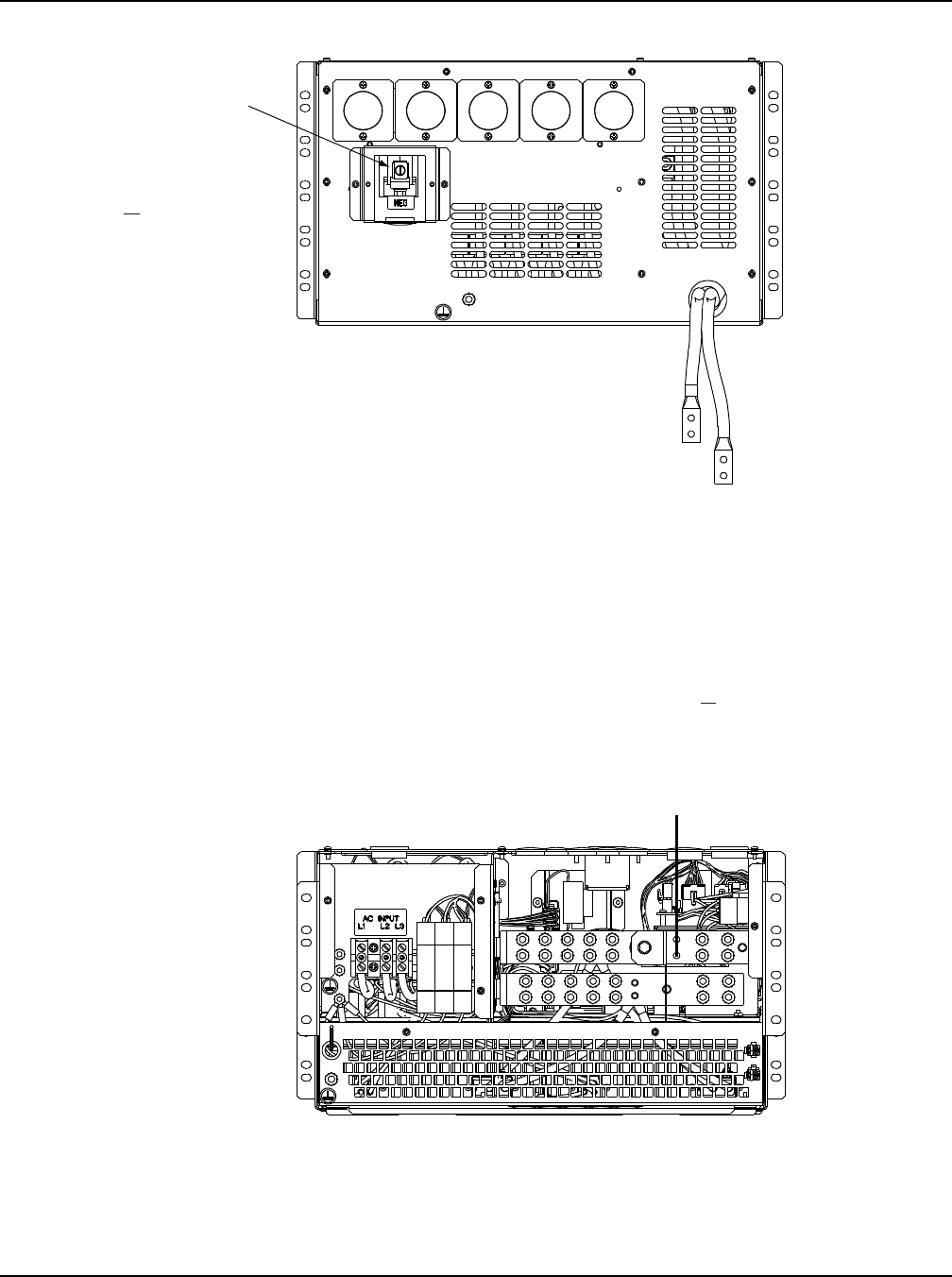
Figure 3-4
Return Busbar (-Bus) Grounding Connection (NPG Configurations Only)
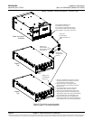
Load Distribution Sub-Rack
Rear View
Rear View
(covers removed)
Power and Control Sub-Rack
Return Busbar (-Bus)
Grounding Point
(NPG Configurations Only)
Note: This connection can be made
here or on the distribution sub-rack
(if furnished) as shown above.
(one set of 1/4-20 x 1/2”
studs on 5/8” centers
for double hole lugs)
(Recommended Torque:
84 in-lbs [9 Nm])
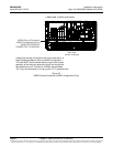
Caution: In the NPG Configuration,
this equipment will have (after installation)
a connection between the earthed conductor
of the DC power supply circuit and the earthing
conductor.
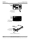
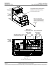
Return Busbar (-Bus)
Grounding Point
(cover removed)
(NPG Configurations Only)
Note: This connection can be
made here or on the power
and control sub-rack as
shown below.
(Wire Size Capacity:
10 AWG to 4 AWG)
(Recomended Torque:
80 in-lbs [9 Nm])