


IM584000300 Installation Instructions
Issue AB, April 3, 2013 Spec. No. 584000300 (Model 4015-X003)
Page 14 Chapter 3. Making Electrical Connections
This document is property of Emerson Network Power, Energy Systems, North America, Inc. and contains confidential and proprietary information owned by Emerson Network Power, Energy
Systems, North America, Inc. Any copying, use, or disclosure of it without the written permission of Emerson Network Power, Energy Systems, North America, Inc. is strictly prohibited.
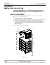
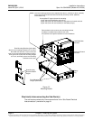
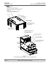
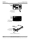
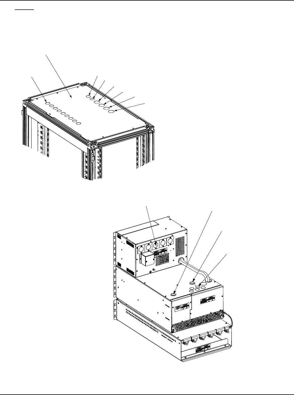
Figure 3-1
Top Feed Cable Landing Diagram – Factory Provided IT Rack
Note: Cables can also be
fed from bottom for raised
floor applications.
Emerson Network
Power DCM IT Rack
* Ground Bar Provided
on Rear of IT Rack
Top Plate
Two options available:
1) P/N 554472.
Holes sized for imperial conduit fittings
(25mm [1”] conduit fittings except AC Input and External
Battery which are 32mm [1.25”] conduit fittings).
2) P/N 554473.
Holes sized for corded connections
using metric cord grips (38mm [1.5”] holes).
AC #1
DC Loads
AC #2
External Battery 1
External Battery 2
Building Ground *
Alarm
Front
Rear
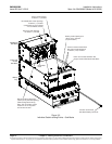
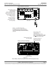
Battery Leads Openings
for 19mm (0.75”) Conduit
(top and bottom)
Distribution
Sub-Rack
Power and
Control
Sub-Rack
Battery
Tray
DC Distribution Leads Openings
for 25mm (1”) Conduit
(snap bushings are furnished
for use without conduit)
AC Input Leads Opening
for 25mm (1”) Conduit
Alarm Leads Opening
for 25mm (1”) Conduit