Installation Instructions IM584000300
Spec. No. 584000300 (Model 4015-X003) Issue AB, April 3, 2013
Chapter 3. Making Electrical Connections Page 25
This document is property of Emerson Network Power, Energy Systems, North America, Inc. and contains confidential and proprietary information owned by Emerson Network Power, Energy
Systems, North America, Inc. Any copying, use, or disclosure of it without the written permission of Emerson Network Power, Energy Systems, North America, Inc. is strictly prohibited.
TASKS TO BE PERFORM FOR ALL INSTALLATIONS
Grounding
Danger: Failure to follow proper grounding procedures can result in electric shock
hazard to personnel or the risk of fire, should a ground fault occur.
For grounding requirements, refer to the current edition of the American National
Standards Institute (ANSI) approved National Fire Protection Association's (NFPA)
National Electrical Code (NEC), applicable local codes, and your specific site
requirements. For operation in countries where the NEC is not recognized, follow
applicable codes.
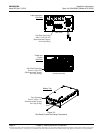
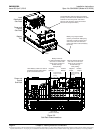
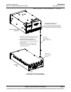
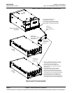
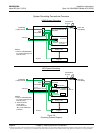
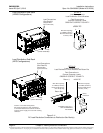
Refer to Figure 3-8 for a complete system grounding scheme diagram.
IT Rack Grounding (Frame Ground)
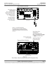
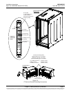
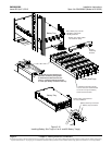
Supply a grounding lead from site ground to the IT rack ground bar. For factory
integrated systems (List R1, R2), refer to Figure 3-9 for connection point.
Note: When the system is furnished in an IT rack, grounding leads are factory wired
from the individual system components to a ground bar located on the rear left
side of the furnished IT rack.
Conduit Grounding (Frame Ground)
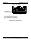
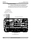
Conduit grounding points are provided on terminal strips located on the left and right
inside side walls of the distribution sub-rack. Refer to Figure 3-9 for connection points.


