


Installation Instructions IM584000300
Spec. No. 584000300 (Model 4015-X003) Issue AB, April 3, 2013
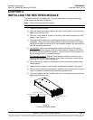
Chapter 3. Making Electrical Connections Page 37
This document is property of Emerson Network Power, Energy Systems, North America, Inc. and contains confidential and proprietary information owned by Emerson Network Power, Energy
Systems, North America, Inc. Any copying, use, or disclosure of it without the written permission of Emerson Network Power, Energy Systems, North America, Inc. is strictly prohibited.
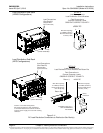
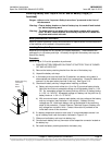
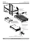
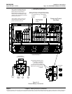
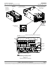
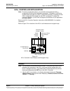
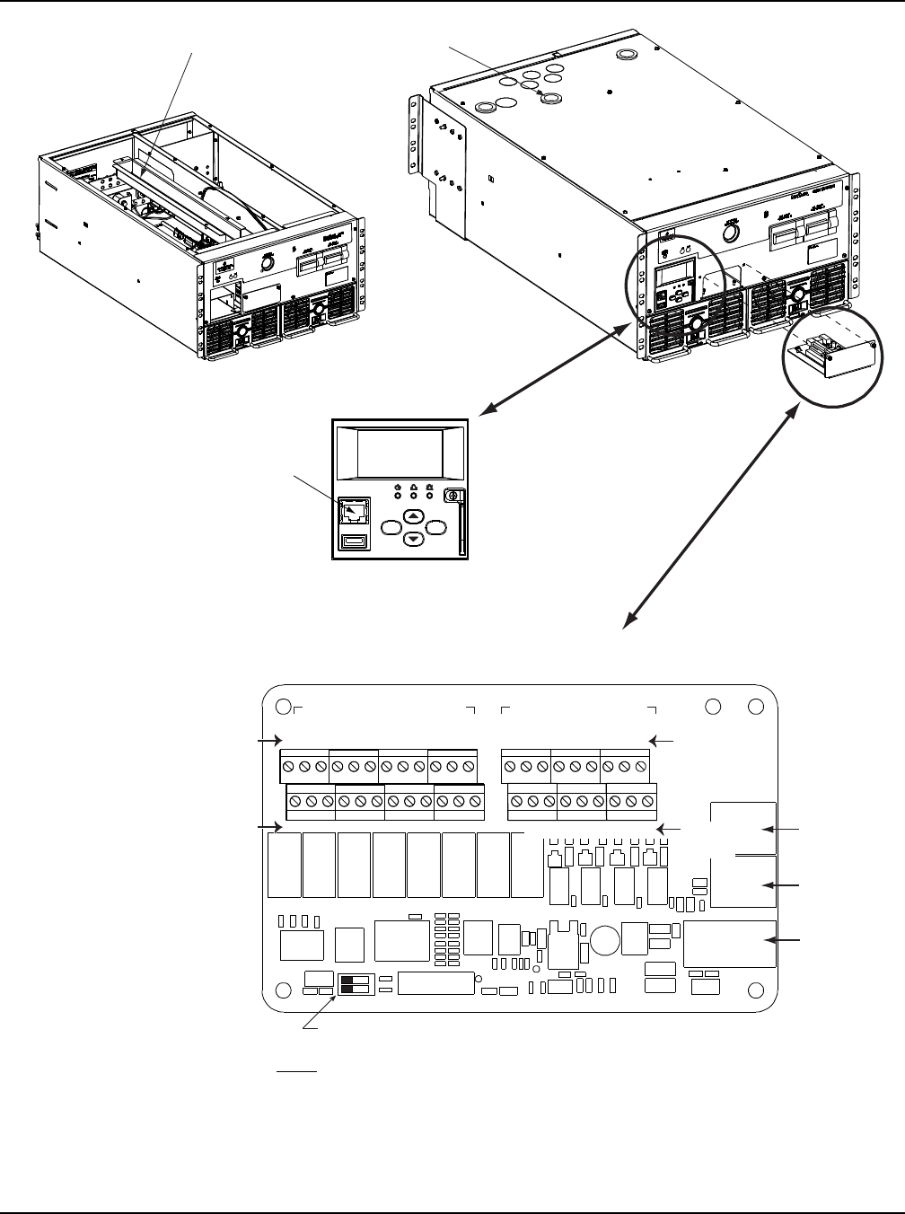
Figure 3-14
External Interface Connections
Customer Input/Output (I/O) Connections
Top View
ACU+ IB2 Interface Board
J1
SW1
J11
J12
Relay Output Term. Blocks Digital Input Term. Blocks
J9 J8 J7 J6 J5 J4 J3
J2
Switch sections must be set to this position
to interface with the ACU+ controller.
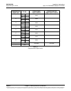
Relay
No.
18 7 6 5 4 3 2
18 7 6 5 4 3 2
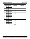
Input
No. (–)
Input
No. (+)
NO C NC
NO NO
C
NC
NO C NC
C
NC
NO C NC
NO
C
NC
NO C NC
NO
C
NC
5 3 1
46 2
5 3 1
46 2
5 3 1
46 2
5
3
1
46 2
5 3 1
46 2
5 3 1
46 2
5
3
1
46 2
8 6 4 2
7 5 3 1
Relay
No.
Connector
to ACU+
IB2 TEMP
PROBE 1
IB2 TEMP
PROBE 2
J3-J9:
Wire Size Capacity: 16-26 AWG (1.5-0.5mm
2
).
Recommended Torque: 2.2 in-lbs (0.25 Nm).
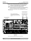
Front
ACU+ IB2
Interface Board
ACU+
ESC ENT
10/100M Ethernet
Port (RJ-45)
I/O Wiring
Cable Tray
Top cover
removed in
illustration for
clarity only.
Power and Control
Sub-Rack
I/O Wiring Opening
for 25mm (1”) Conduit