


IM584000300 Installation Instructions
Issue AB, April 3, 2013 Spec. No. 584000300 (Model 4015-X003)
Page 24 Chapter 3. Making Electrical Connections
This document is property of Emerson Network Power, Energy Systems, North America, Inc. and contains confidential and proprietary information owned by Emerson Network Power, Energy
Systems, North America, Inc. Any copying, use, or disclosure of it without the written permission of Emerson Network Power, Energy Systems, North America, Inc. is strictly prohibited.
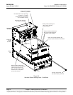
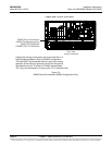
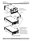
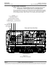
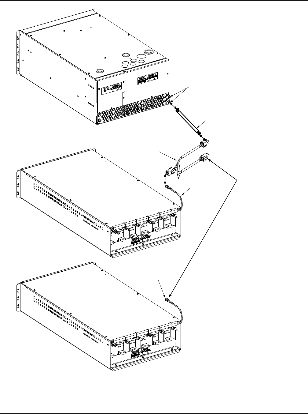
Figure 3-7 (cont’d from previous page)
Internal Battery Tray Interconnections
Battery Tray
Control/Alarm
Daisy Chain Cable
(P/N 553614)
Internal/External Battery Tray
Control/Alarm Connectors
(If an internal or external battery tray is
not connected, MUST have termination
plugs installed.) (Use either connector.)
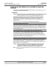
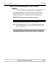
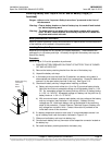
1. Remove a termination plug from one of the
connectors (either one) located on the rear
of the power and control sub-rack.
2. Plug the extension control/alarm cable
into the connector the termination plug was
removed from.
3. Connect the other end of the extension
control/alarm cable into the end of the
battery tray control/alarm daisy chain cable.
4. Plug the center connector of the battery tray
control/alarm daisy chain cable into the battery
tray control/harness of the first battery tray.
5. Plug the remaining end of the battery tray
control/alarm daisy chain cable into the battery
tray control/harness of the second battery tray.
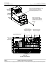
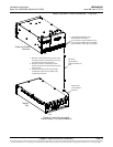
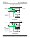
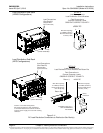
Rear
Rear
Battery Tray
Control/Alarm
Harness
Power and Control
Sub-Rack
Battery
Tray
Rear
Battery Tray
Control/Alarm
Harness
Battery
Tray
Extension
Control/Alarm
Cable (P/N 554715)
(56”)
Battery Tray Alarm / Control Connections - 2 or More Trays