


Installation Instructions IM584000300
Spec. No. 584000300 (Model 4015-X003) Issue AB, April 3, 2013
Chapter 2. Installing the System Page 11
This document is property of Emerson Network Power, Energy Systems, North America, Inc. and contains confidential and proprietary information owned by Emerson Network Power, Energy
Systems, North America, Inc. Any copying, use, or disclosure of it without the written permission of Emerson Network Power, Energy Systems, North America, Inc. is strictly prohibited.
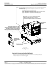
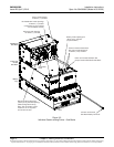
e) Secure the rear mounting brackets to the power and control sub-rack with the
furnished hardware (hardware is installed from inside the sub-rack, the rear
mounting brackets have captive fasteners).
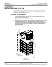
3) If furnished, the battery tray(s) is typically installed at the bottom of the IT rack
due to the weight of the batteries.
Note: Only install the battery tray(s) at this time. Battery sub-trays (with
batteries) will be installed in the “Making Electrical Connections” section.
Note: The system can consist of 0-5 battery tray(s).
Note: Battery cables from the battery tray(s) can enter the power and control
sub-rack from either the top or bottom of the power and control sub-rack.
Note that a space is required between the power and control sub-rack
and battery tray to allow the cables to enter from the bottom.
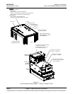
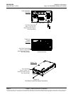
a) Secure the rear mounting brackets to the IT rack with the furnished cage nuts
and screws.
b) Slide the battery tray into the front of the IT rack until it is in position (with the
bottom of the sub-rack resting on the angles of the rear mounting brackets).
c) Secure the front mounting flanges to the IT rack with the furnished cage nuts
and screws.
d) Secure the rear mounting brackets to the battery tray with the furnished
hardware (hardware is installed from inside the battery tray, the rear
mounting brackets have captive fasteners).
e) Repeat this procedure if other battery tray(s) are furnished.