


IM584000300 Installation Instructions
Issue AB, April 3, 2013 Spec. No. 584000300 (Model 4015-X003)
Page 12 Chapter 2. Installing the System
This document is property of Emerson Network Power, Energy Systems, North America, Inc. and contains confidential and proprietary information owned by Emerson Network Power, Energy
Systems, North America, Inc. Any copying, use, or disclosure of it without the written permission of Emerson Network Power, Energy Systems, North America, Inc. is strictly prohibited.
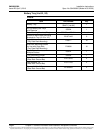
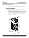
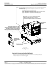
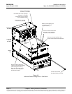
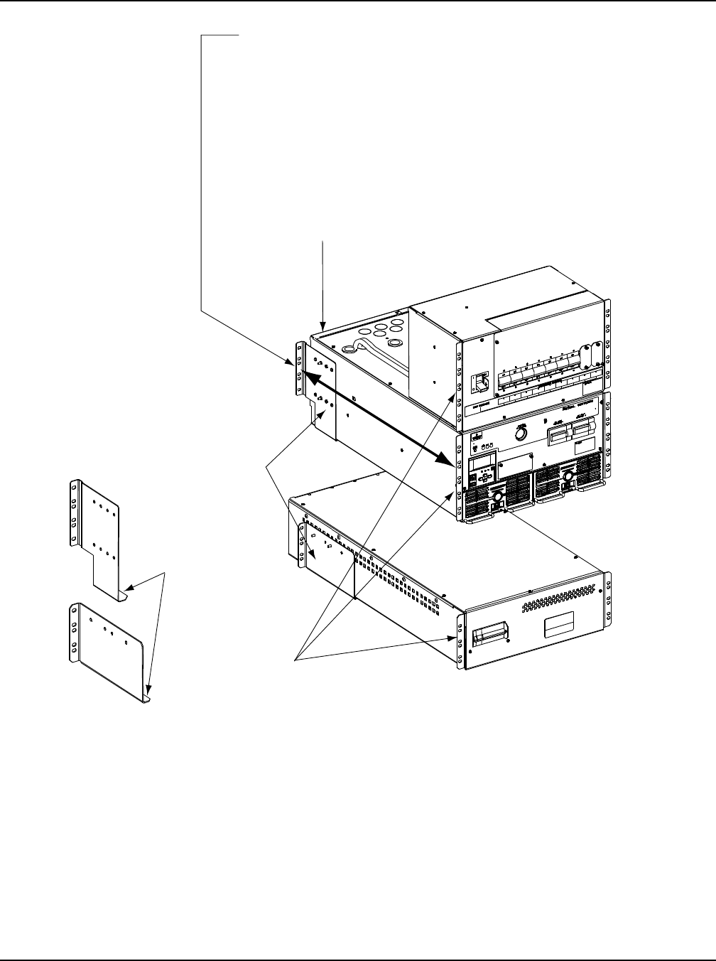
Figure 2-2
Mounting Details
Electrically Interconnecting the Sub-Rack(s)
The sub-racks are electrically interconnected later in the “Sub-Racks Electrical
Interconnections” procedure on page 21.
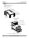
Front
Use supplied IT cage nut/screw for mounting.
(3) per side for the distribution sub-rack(s).
(4) per side (front and rear brackets) for the power and control sub-rack.
(3) per side (front and rear brackets) for the battery tray(s).
Front Mounting
Flanges (both sides)
Rear Mounting
Brackets Bottom
Angles
The rear mounting bracket can be adjusted from 28.75” (730mm) to 32.25” (819mm)
for the Power and Control Sub-Rack and 26.39” (670mm) to 32.60” (828mm)
for the Batter Tray.
Rear Mounting Brackets (both sides)
(Secure rear mounting brackets to IT rack first,
then slide sub-rack into IT rack so sub-rack
rests on rear mounting brackets bottom angles,
then secure sub-rack’s front mounting flanges
to IT rack, and finally secure rear mounting
brackets to sub-rack.)
Remove back cover to secure rear mounting brackets,
hardware is installed from inside the sub-rack,
the brackets have captive fasteners to secure hardware.
Load Distribution
Sub-Rack
Power and Control
Sub-Rack
Battery
Tray