


IM584000300 Installation Instructions
Issue AB, April 3, 2013 Spec. No. 584000300 (Model 4015-X003)
Page 26 Chapter 3. Making Electrical Connections
This document is property of Emerson Network Power, Energy Systems, North America, Inc. and contains confidential and proprietary information owned by Emerson Network Power, Energy
Systems, North America, Inc. Any copying, use, or disclosure of it without the written permission of Emerson Network Power, Energy Systems, North America, Inc. is strictly prohibited.
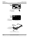
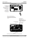
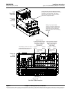
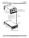
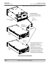
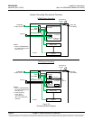
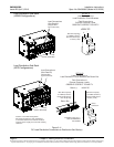
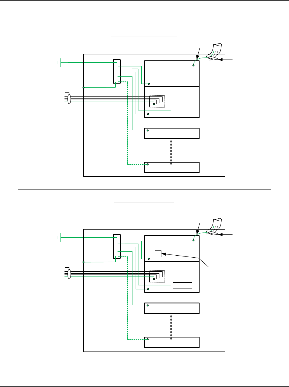
Figure 3-8
Grounding Scheme Diagram
NPG System Grounding
HRMG System Grounding
DC Load Distribution
Sub-Rack
Power & Control
Sub-Rack
Battery Tray
AC Input
HRMG Ground
Connection
IT Rack
Main
Ground Bar
To Building
Facility Ground
Rack Frame Ground
Tray 2-5
NOTES:
1. Refer to SAG584000300
for recommended ground
lead wire sizes.
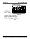
NOTES:
1. Refer to SAG584000300
for recommended ground
lead wire sizes.
2. -400V DC Return
can be either
connected to the
-Bus or DC Distribution
Sub-Rack.
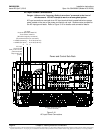
System Grounding Connections Overview
±200V DC
Load Wiring
+ -
Conduit Gnd
(if req’d)
DC Load Distribution
Sub-Rack
Power & Control
Sub-Rack
Battery Tray
AC Input
IT Rack
Main
Ground Bar
To Building
Facility Ground
Rack Frame Ground
Tray 2-5
400V DC
Load Wiring
+ -
Conduit Gnd
(if req’d)
Note 2
- BUS
IT Rack
IT Rack