


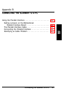

Using the Parallel Interface
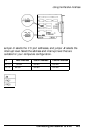
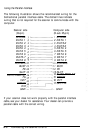
The following illustration shows the recommended wiring for the
bidirectional parallel interface cable. The dotted lines indicate
wiring that is not required for the scanner to communicate with the
computer.
Scanner side
(36-pin)
STROBE
DATA 1
DATA 2
DATA 3
DATA 4
DATA 5
DATA 6
DATA 7
DATA 8
ACKNLG
BUSY
PE
SLCT
AUTO FEED XT
FG
INIT
ERROR
DIR
GND
Computer side
(D-sub 25-pin)
1
STROBE
2
DATA 1
3
DATA2
4
DATA3
5
DATA 4
6
DATA 5
7
DATA 6
8
DATA 7
9
DATA 8
10
ACKNLG
11
BUSY
12
PE
13 SLCT
14 AUTO FEED XT
15 ERROR
16 INIT
17 SLCT IN
- GND
If your scanner does not work properly with the parallel interface
cable, see your dealer for assistance. Your dealer can provide a
parallel cable with the correct wiring.
B-6
Connecting the Scanner to a PC