


CHAPTER 8 Expansion Disk Cabinet
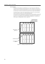
Rear Panel
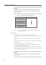
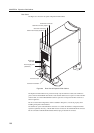
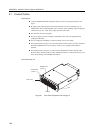
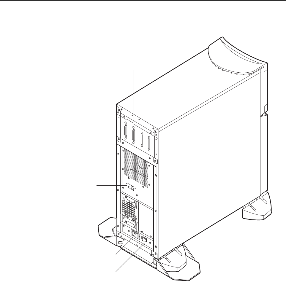
The Figure 8.3 shows the rear panel of Expansion Disk Cabinet.
AC Main Line Switch
AC Power Input
Service Pin
SCSI IN Connector( Standard )
SCSI IN Connector( Option )
SCSI OUT Connector
SCSI OUT Connector
RCI Port
Power Supply Unit
( Standard )
Figure 8.3 Rear View of Expansion Disk Cabinet
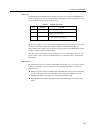
The Expansion Disk Cabinet is not powerd on/off by only the main line switch, but it is linked to
power on/off of the GP7000F main cabinet. Note that this cabinet does not power on if the main line
switch is OFF, even if the GP7000F main cabinet is powered on. Keep the main line switch set to
ON for regular use.
Be sure to set the RCI configuration, which is detailed in Chapter13 , must be set properly when
installing an Expansion Disk Cabinet.
The cabinet has 2 pair of SCSI IN/OUT connectors on it. When the cabinet is configured without
expansion (optional) drive bays, a SCSI cable must be connected to the standard SCSI IN connector.
Be sure to install an UltraSCSI differential terminator plug on SCSI OUT connector.
100