


CHAPTER 11 Input-Output Units
Front Panel
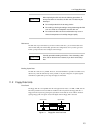
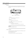
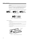
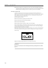
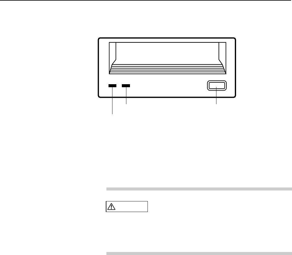
The DAT unit has two LEDs and Eject switch as shown in Figure 11.5 .
Tape
Clean
2 Active LED
3 Attention LED
1 Eject switch
Figure 11.5 DAT Unit Front Panel
This section describes the functions of the switches and LEDs of the DAT unit.
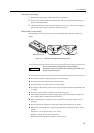
1 Eject switch
A data cartridge can be removed by pressing the eject switch. If the processor inhibits
removal of a data cartridge, it cannot be removed by pressing the eject switch.
CAUTION
Data destruction: Do not press the eject switch during
an operation (when the tape LED is blinking). If the
eject switch is held down for about 5 seconds or
pressed 3 times within a 5-minutes period, the forced
ejection function will be executed and the data being
written may be destroyed.
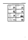
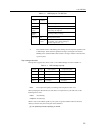
2 Active LED
The Active LED lights steady when the data cartridge is loaded and the tape unit is
ready to operate. The Active LED blinks when the tape unit is operating. For details,
refer to Table 11.3 .
3 Attention LED
When the Attention LED blinks, the head of the tape unit should be cleaned using a
cleaning tape or a cartridge is near the end of it’s useful life. The Attention LED
lights steady on continuously when the tape unit fails. For details, refer to Table 11.3 .
130