


10.2 Device Configuration
10.2 Device Configuration
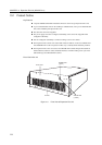
This file unit consists of the following components.
Rack mount cabinet
Basic power supply and expansion option power supply (for redundant configuration)
DC-DC converter
Cooling fans (redundant configuration)
SCSI-BP boards
Interface board
Hot-swappable disk drives
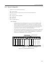
Disk configuration
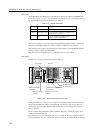
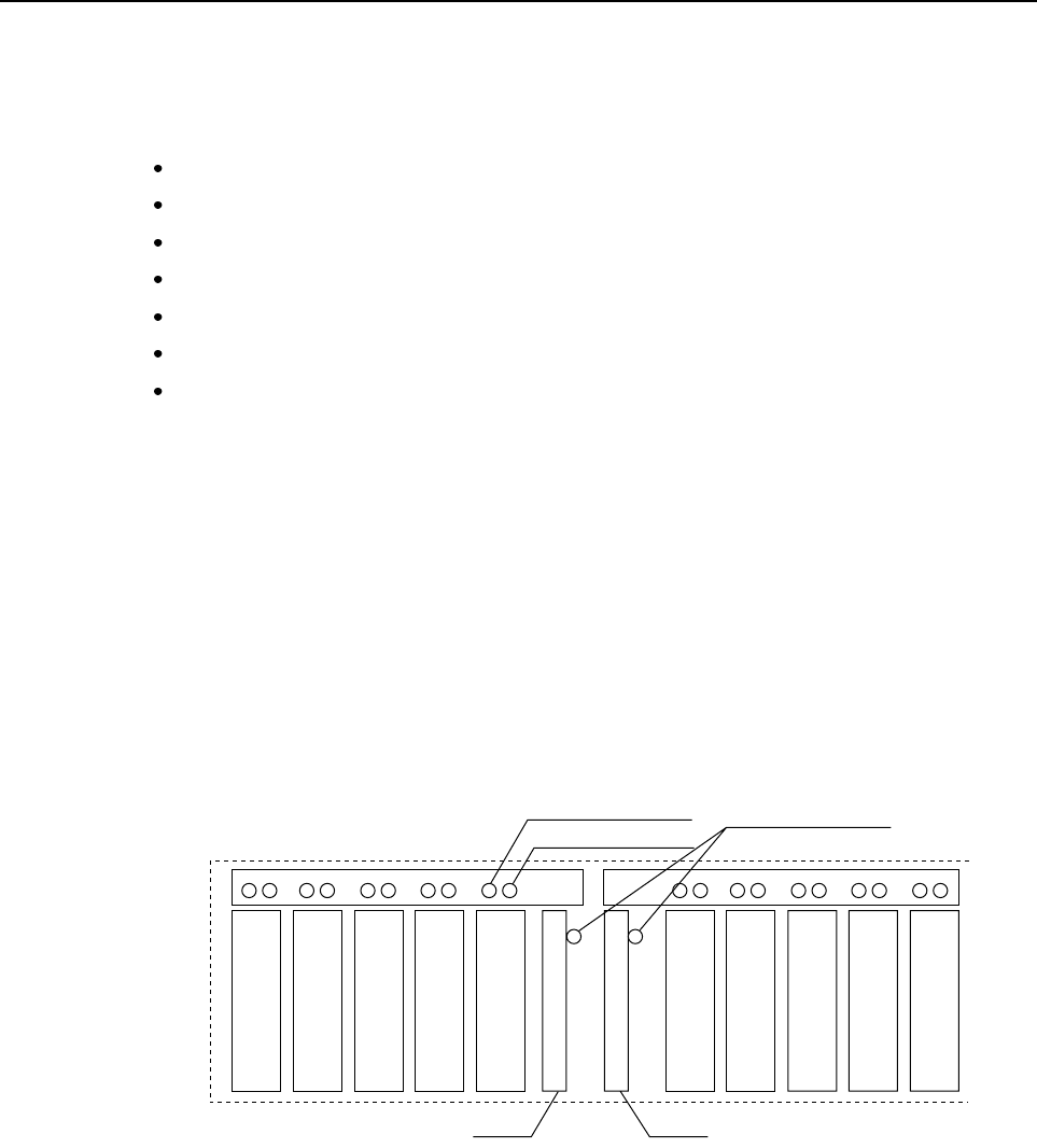
The Expansion File Unit has 2 UltraSCSI buses. Up to 5 drive units can be installed in the half
portion of the cabinet as indicated in Figure 10.2 . Internally, they are connected to an interface
board by a single-ended UltraSCSI bus. And, up to 5 drive units can be installed another half
portion of the cabinet. Also, they are connected to an interface board by a single-ended UltraSCSI
bus. The interface board has a single-ended to differential interface converter in it, and each
interface board is connected to the host by a differential UltraSCSI bus.
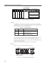
Each interface board has a POWER LED. If a FAULT LED and an ACTIVE LED of a disk bay that
has a disk drive doesn’t light up, check the POWER LED on the interface board in the cage if it is
light up or not. A failed unit can be isolated by checking this POWER LED, a ACTIVE LED, a
FAULT LED, and a POWER LED on the power supply unit.
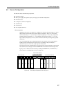
#1 #2 #3 #4 #5 #1 #2 #3 #4 #5
ACTIVE LED (Green)
FAULT LED (Amber)
POWER LED (Green)
Interface Board (Standard)
Interface Board (Option)
Figure 10.2 Drive Bays of Expansion File Unit
115