


CHAPTER 12 External Interfaces
Connection of signal lines
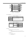
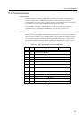
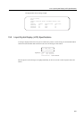
Figure 12.2 shows a configuration of signal line on connecting DCE device.
SD
RD
RS
Controller/
adapter
(DTE)
I/O Device
(DTE)
CS
ER
DR
CD
ST1
ST2
RT
SG
[Send Data]
[Receive Data]
[Request to Send]
[Clear to Send]
[Equipment Ready]
[Data set Ready]
[Carrier Detect]
[Send Timing 1]
[Send Timing 2]
[Receive Timing]
[Signal Ground]
Figure 12.2 Configuration of Signal Line when Connecting DCE Device(Example)
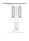
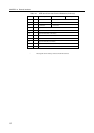
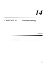
The configuration of the signal line on connecting DTE device is shown below.
SD
RD
ER
DR
RS
CS
CD
ST1
ST2
RT
SG
SD
RD
ER
DR
RS
CS
CD
ST1
ST2
RT
SG
Main cabinet side
Note:
RS/CS flow control cannot be achieved by
this wiring
I/O device side
Figure 12.3 Configuration of Signal Line when Connecting DTE Line(Example)
150